WSHP-PRC004-EN22
Tracer ZN.510
Controls
Features and
Benefits
High and Low Pressure Safety Controls
The Tracer ZN.510 controller detects the
state of the high pressure or low
pressure switches. When a fault is
sensed by one of these switches, the
corresponding message is sent to the
Tracer ZN.510 controller to be logged
into the fault log. When the circuit
returns to normal, the high pressure
control and low pressure control
automatically reset. If a second fault is
detected within a thirty-minute time
span, the unit must be manually reset.
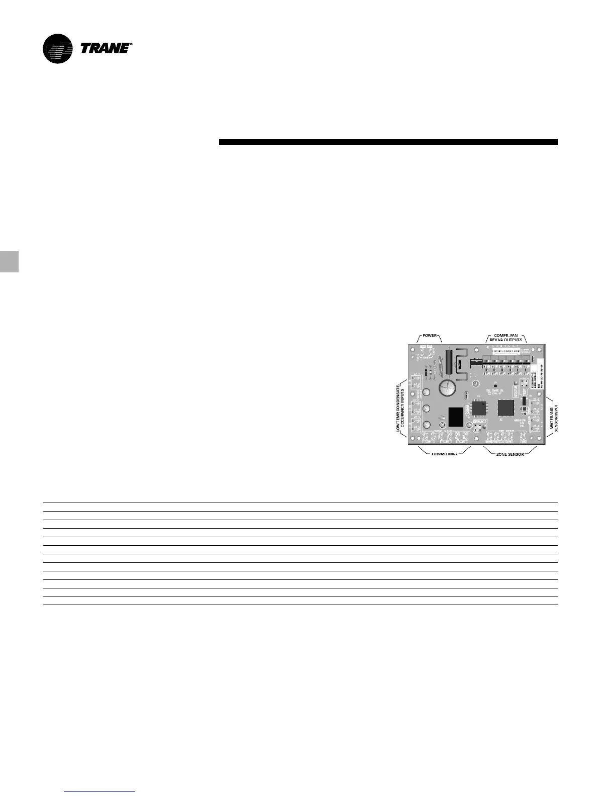
Tracer ZN.510 Board
The application drawing in Figure FB-37
references component device
connections to the Tracer ZN.510 board.
Three LED’s (light emitting diodes) are
provided for indicating the operating
mode of the controller. See Table FB-5
for LED specifics.
Table FB-5 – Tracer ZN.510 LED’s
LED Activity Description
RED LED OFF continuously when power is applied to the controller Normal operation
RED LED ON continuously, even when power is applied to the controller Someone is pressing the service button or the controller has failed
RED LED FLASHES once every second Restore the unit to normal operation with Rover
TM
GREEN LED ON continuously Power ON (normal operation)
GREEN LED BLINKS (one blink) Manual output test mode. No diagnostics present
GREEN LED BLINKS (two blinks) Manual output test mode. One or more diagnostics present
GREEN LED BLINKS (1/4 second on/off for 10 seconds) WINK mode for controller identification
GREEN LED OFF Power off. Abnormal condition. Test button is pressed.
YELLOW LED OFF continuously Controller not detecting communication
YELLOW LED BLINKS Controller detects communication
YELLOW LED ON continuously Abnormal condition
Condensate Overflow
When condensate reaches the trip point,
a condensate overflow signal generates
a diagnostic which disables the fan, unit
water valves (if present), and
compressor. The unit will remain in a
halted state until the condensation
returns to a normal level. At this time,
the switch in the drain pan will
automatically reset. However, the
controller’s condensate overflow
diagnostic must be manually reset to
clear the diagnostic and restart the unit.
Figure FB-37 – Tracer ZN.510 Board