64
WSHP-SVX01AA-EN
5. Locate the entering water sensor that is located
behind the unit’s control box, and wire tie it to the
water SUPPLY side of the piping. The sensor must
be mounted before the two-position valve.
Attaching the sensor anywhere else will cause the
WSE to not operate correctly. Bundle up any excess
sensor wire and wire tie the bundle neatly.
6. Locate the WSE valve wires (35B (COM), 36B
(OPEN), 37B (CLOSE)) behind control box, and
connect to the valve actuator. Bundle up any excess
wire and wire tie the bundle neatly. Direction of
rotation is reversible with switch.
7. Insulate the economizing piping package and the
associated hoses via field pipe insulation Insulating
the piping will prevent condensation from forming
on the pipe and dripping on the floor.
NNootteess::
• Trane does not provide insulation on the
economizing piping package. This insulation
must be field provided and field installed.
• Trane does not provide condensate
overflow protection of the waterside
economizer. This must be field provided and
installed.
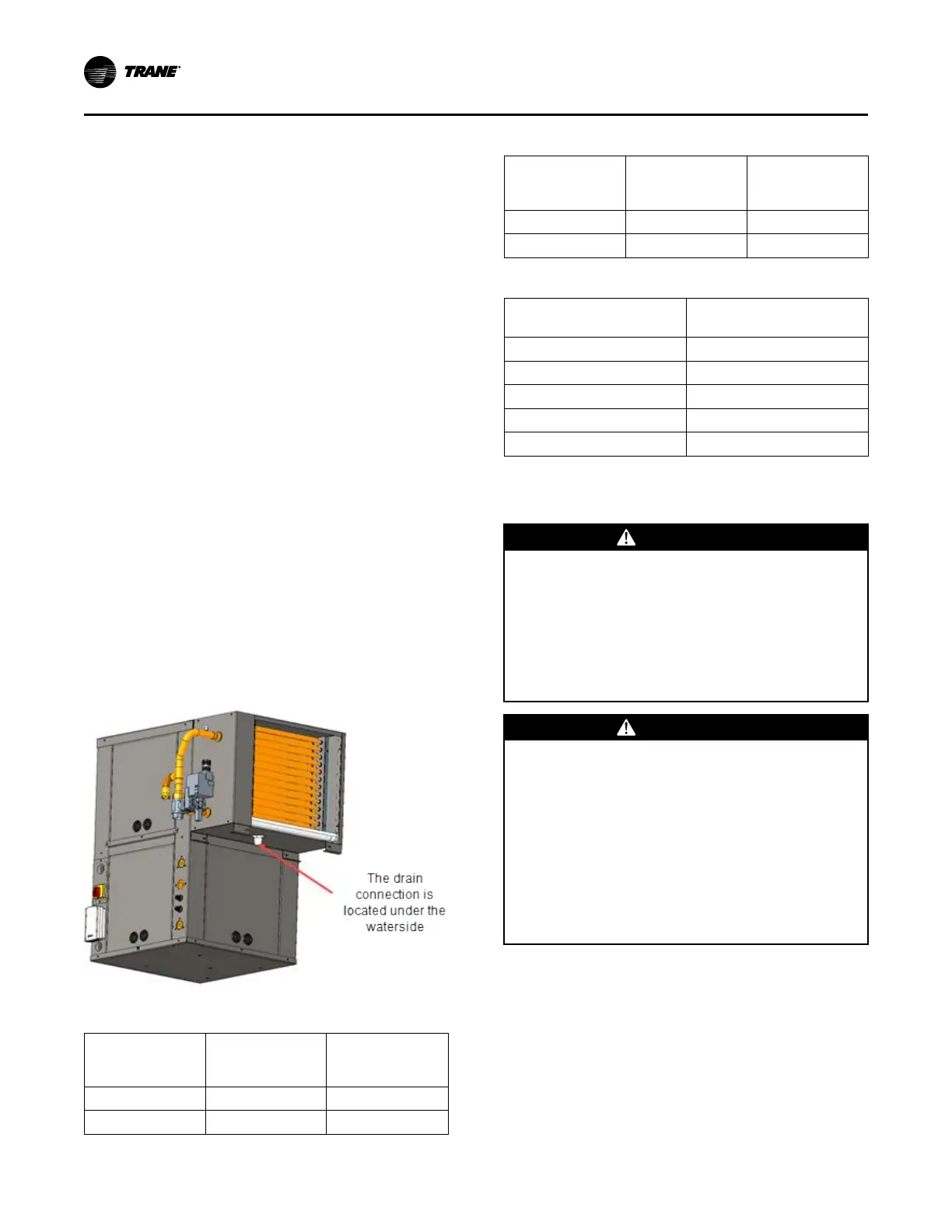
8. Field pipe the drain lines of the waterside
economizer and water-source heat pump together
prior to installing a condensate trap for proper
trapping of condensation (see Figure 76, p. 63). The
vertical units will be piped similar to the horizontal
units.
Figure 81. Step 8
Table 45. Economizer part numbers
GEH Unit 60 Hz GEH Unit 50 Hz
Waterside
Economizer
Part Number
006-015 006-012 4476 1418 0001
018-030 015-024 4476 1419 0001
Table 45. Economizer part numbers (continued)
GEH Unit 60 Hz GEH Unit 50 Hz
Waterside
Economizer
Part Number
035-042 030-036 4476 1420 0001
048-060 042-060 4476 1421 0001
Table 46. Economizer part numbers
GEVG Unit 60 Hz
Waterside Economizer
Part Number
006-012 WSHPECN00001
015–018 WSHPECN00002
024–030 WSHPECN00003
036–042 WSHPECN00004
048–060 WSHPECN00005
Waterside Economizer Installation for
GEH and GEV 6 to 25 Ton Models
WWAARRNNIINNGG
HHaazzaarrddoouuss VVoollttaaggee!!
FFaaiilluurree ttoo ddiissccoonnnneecctt ppoowweerr bbeeffoorree sseerrvviicciinngg ccoouulldd
rreessuulltt iinn ddeeaatthh oorr sseerriioouuss iinnjjuurryy..
DDiissccoonnnneecctt aallll eelleeccttrriicc ppoowweerr,, iinncclluuddiinngg rreemmoottee
ddiissccoonnnneeccttss bbeeffoorree sseerrvviicciinngg.. FFoollllooww pprrooppeerr
lloocckkoouutt//ttaaggoouutt pprroocceedduurreess ttoo eennssuurree tthhee ppoowweerr
ccaann nnoott bbee iinnaaddvveerrtteennttllyy eenneerrggiizzeedd.. VVeerriiffyy tthhaatt nnoo
ppoowweerr iiss pprreesseenntt wwiitthh aa vvoollttmmeetteerr..
WWAARRNNIINNGG
PPrrooppeerr FFiieelldd WWiirriinngg aanndd GGrroouunnddiinngg
RReeqquuiirreedd!!
FFaaiilluurree ttoo ffoollllooww ccooddee ccoouulldd rreessuulltt iinn ddeeaatthh oorr
sseerriioouuss iinnjjuurryy..
AAllll ffiieelldd wwiirriinngg MMUUSSTT bbee ppeerrffoorrmmeedd bbyy qquuaalliiffiieedd
ppeerrssoonnnneell.. IImmpprrooppeerrllyy iinnssttaalllleedd aanndd ggrroouunnddeedd
ffiieelldd wwiirriinngg ppoosseess FFIIRREE aanndd EELLEECCTTRROOCCUUTTIIOONN
hhaazzaarrddss.. TToo aavvooiidd tthheessee hhaazzaarrddss,, yyoouu MMUUSSTT ffoollllooww
rreeqquuiirreemmeennttss ffoorr ffiieelldd wwiirriinngg iinnssttaallllaattiioonn aanndd
ggrroouunnddiinngg aass ddeessccrriibbeedd iinn NNEECC aanndd yyoouurr llooccaall//
ssttaattee//nnaattiioonnaall eelleeccttrriiccaall ccooddeess..
1. Remove the filter frame from the unit.
2. Remove the waterside service panel from the unit.
3. Remove the control box service panel from the unit.
4. Remove the economizer and miscellaneous
mounting parts from it’s packaging.
5. GEV ONLY: Mount the economizer support angle
(4475 1637 0100) found in the economizer
packaging in the same holes of the return air filter
frame removed in Step 1. The support angle screws
into the unit roof.
IInnssttaallllaattiioonn