128
RT-SVX063G-EN
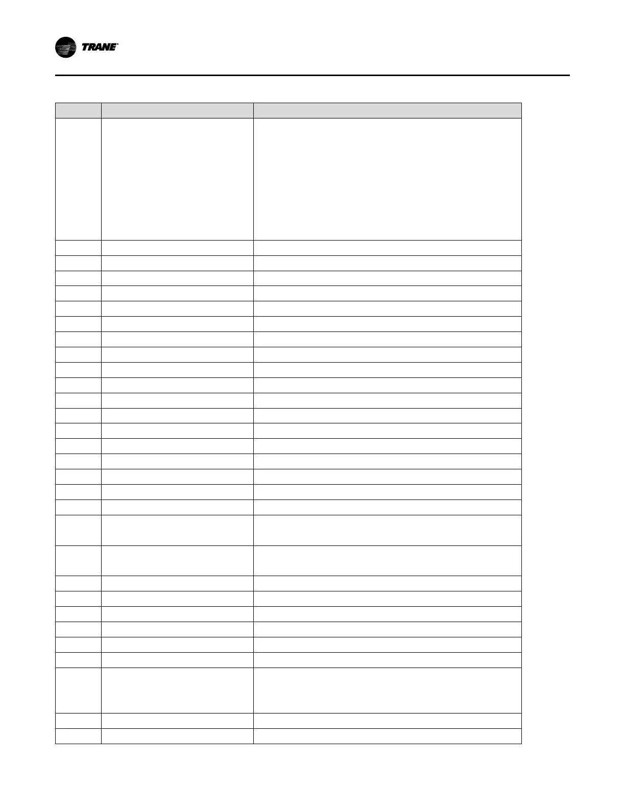
Table 71. Supply fan VFD programming parameters (continued)
ID
Description Parameter Setting
0-06
Grid Type
Set to applicable unit power supply
[102] 200-240V/60Hz for 208 & 230V/60Hz units
[122] 440-480V/60Hz for 460V/60Hz units
[132] 525-600V/60Hz for 575V/60Hz units
[12] 380-440V/50Hz for 380 & 415V/50Hz supply
For IT Grid (no ground connections) or Corner grounded Delta power supply
systems, the applicable voltage/Hz and IT-Grid or Delta should be selected.
0-40
[Hand on] Key on LCP [0] Disabled
1-20 Motor Power
Per Motor Nameplate HP
1-22
Motor Voltage (V) Per Motor Nameplate Voltage
1-23
Motor Frequency (Hz) Per Motor Nameplate Frequency
1-24
Motor Current (A) Per Motor Nameplate FLA
1-25
Nominal Speed (RPM) Per Motor Nameplate Rated Speed
1-73
Flying Start [1] Enabled
1-90 Motor Thermal Protection
[4] ETR Trip1
2-00
DC Hold/Preheat Current (%) [0] 0%
2-01
DC Brake Current (%) [0] 0%
2-04
DC Brake Cut In Speed (Hz) [10] 10Hz
3-02
Minimum Reference (Hz) Per Unit Nameplate - Evap Fan VFD Min Hz
3-03
Maximum Reference (Hz) Per Unit Nameplate - Evap Fan VFD Max Hz
3-15 Reference 1 Source
[1] Local bus reference
3-16 Reference 2 Source
[0] No function
3-17 Reference 3 Source
[0] No function
3-41
Ramp 1 Ramp Up Time (s) [30] 30s
3-42
Ramp 1 Ramp Down Time (s) [30] 30s
4-12
Motor Speed Low Limit (Hz)
[20] 20Hz for 4 Pole
[18] 18Hz for 6 Pole
4-14
Motor Speed High Limit (Hz)
See Table 18 for value
4-18
Current Limit (%) [100] 100%
4-19
Max Output Frequency (Hz) [120] 120Hz
5-10
Terminal 18 Digital Input [0] No Operation
5-12
Terminal 27 Digital Input [0] No Operation
5-13
Terminal 29 Digital Input [0] No Operation
8-30 Protocol
[2] Modbus RTU
8-31 Address
Set address per unit component location diagram
[7] for 4TB1
[8] for 4TB2
8-32 Baud Rate
[7] 115200 Baud
8-33
Parity / Stop Bits [0] Even Parity, 1 Stop Bits
Service and Maintenance
 Loading...


