RT-SVX063G-EN
43
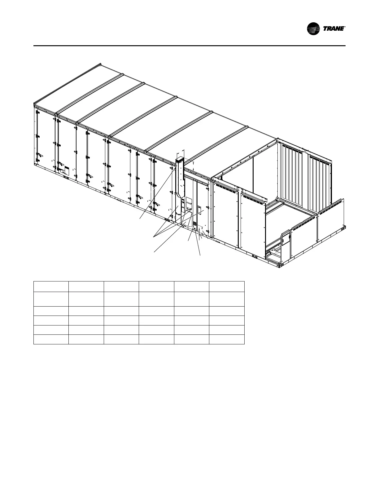
Figure 26. Gas heat component dimensions
A
B
C
D
Combustion
inlet rain shield
(40-75 ton only)
Gas pipe
entry with
grommet
CPVC Drain
Heat access
(850 MBH shown)
Flue Vent
Note: See gas piping figures for NPT size
Tonnage
Heater Size A B C D
20–30
250, 350 & 500
MBh
6.75 7.59 5.29 7.85
40–55 350 MBh 6.75 11.85 5.42 11.58
40–75 500 MBh 6.75 11.85 5.42 11.58
40–75 850 MBh 10.5 18.0 5.42 11.58
60–75 1200 MBh 10.5 13.35 5.42 11.58
Connecting the Gas Supply Line to the
Furnace Gas Train
Follow the steps below to complete the installation between
the supply gas line and the furnace. Refer to the following
figures, for the appropriate gas train configuration.
1. Connect the supply gas piping using a “ground-joint”
type union to the furnace gas train and check for leaks.
2. Adjust the inlet supply pressure to the recommended 7"
to 14" w.c. parameter for natural gas (11" to 14" w.c. for
propane).
3. Ensure that the piping is adequately supported to avoid
gas train stress.
Installation
 Loading...


