60
RT-SVX063G-EN
If adjustment is needed, adjust the regulator on the
valve. Refer to , p. 60 for two stage valve on 250 & 350
MBh two stage, and Figure 35, p. 61 for one stage
valve on all other multi-stage and modulating burners,
for the adjustment screw location. Turn the screw
clockwise to increase the gas pressure or
counterclockwise to decrease the gas pressure.
Combustion Air Analysis
1. Using a flue analyzer make note of the oxygen, carbon
dioxide, and the Air Free CO levels. Take several
samples to assure an accurate reading.
Important: The flue reading should be taken from
center of flue and at least 4 inches down
from the outlet.
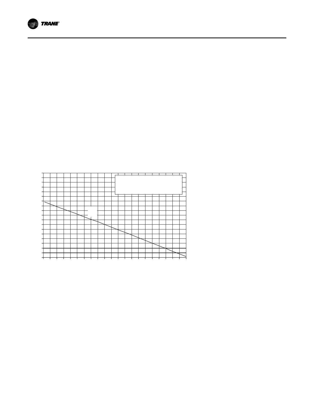
2. Compare the measured oxygen level to the combustion
curve in Figure 34, p. 60. The oxygen content of the
flue gas should be 4% to 5%. If the oxygen level is
outside this range, contact the Technical Support for
assistance.
Low-Fire Adjustment (250 and 350 MBH
Two Staged only)
1. Use the TEST initiation procedures outlined in the
previous section to operate the furnace in the low-fire
state (1st Stage).
2. Check the manifold gas pressure of the valve by using
the pressure port on the manifold section downstream
of the valve. The manifold pressure for Low Fire First
Stage should be set to 1.2" w.c. (3.0" w.c. for propane).
If adjustment is needed, adjust the LO regulator on the
two stage valve. Refer to , p. 60 for the adjustment
screw location. Turn the screw clockwise to increase
the gas pressure or counterclockwise to decrease the
gas pressure.
3. Check the oxygen, carbon dioxide, and the Air Free CO
levels after each adjustment.
4. Tap the STOP button on the User Interface to stop the
system operation.
Figure 34. Natural gas combustion curve (ratio of oxygen to carbon dioxide in percent)
0
1
2
3
4
5
6
7
8
9
10
11
12
13
14
15
16
17
18
0 1 2 3 4 5 6 7 8 9 10 11 12 13 14 15 16 17 18 19 20 21
Percent Carbon Dioxide
Percent Oxygen
A =
A
Curve Fuel
1,000 BTU per cu ft.
of Natural Gas
Startup the Unit
 Loading...


