PKGP-SVX010A-EN
17
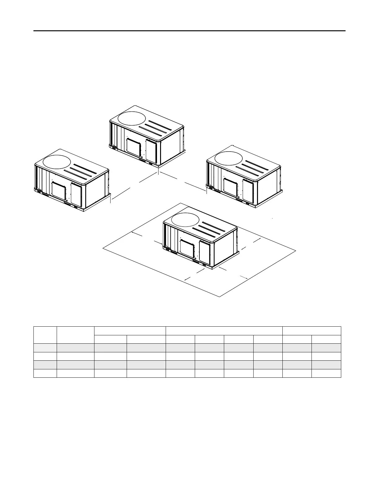
Clearances
Figure 9, p. 17 illustrates the minimum operating and
service clearances for either a single or multiple unit
installation. These clearances are the minimum distances
necessary to assure adequate serviceability, cataloged unit
capacity, and peak operating efficiency. Providing less than
the recommended clearances may result in condenser coil
starvation, “short-circuiting” of exhaust and economizer
airflows, or recirculation of hot condenser air.
Figure 9. Typical installation clearances for single and multiple unit applications
Side by Side
Note 1
End to End
Note 1, 2
7’0”
2134 MM
6’0”
1829 MM
3’0”
914 MM
Single Unit
3’0”
914 MM
3’0”
914 MM
4’0”
1219 MM
Notes:
1. When equipped with economizer
or barometric relief damper, clearance
distance is to be measured from
protruding hood instead of base.
2. Clearance is the same if any unit
is rotated 180 degrees.
4’0”
1219 MM
for D cabinet
5’0”
1525 MM
for D cabinet
5’8” for D cabinet
1727 MM
Weights
Table 1. Model weights, corner weights (lbs) and center of gravity dimensions (in.)
Tons Unit Model No.
Model Weights
(a)
Corner Weights
(b)
Center of Gravity (in.)
Shipping
Net A B C D
Length
Width
12.5 WSJ150 2225 2005 688 487 344 486 51 36
15 WSJ180 2246 2026 695 492 348 491 51 36
20 WSJ240 2403 2183 680 550 426 527 55 38
25 WSJ300 2405 2185 680 550 427 528 55 38
(a)
Weights are approximate. Weights do not include additional factory or field installed options/accessories. For option/accessory additional weights to be added to unit weight,
reference the following table.
(b)
Corner weights are given for information only.
Dimensional Data