SS-SVX11K-EN
77
Discharge Air Sensor (Honeywell 6RT3 or
Honeywell 8RT3)
Each unit ordered with variable air volume controls
(digit 9 in the model number) is shipped with a
Honeywell 6RT3 or 8RT3 discharge air sensor.
WWAARRNNIINNGG
HHaazzaarrddoouuss VVoollttaaggee!!
FFaaiilluurree ttoo ddiissccoonnnneecctt ppoowweerr bbeeffoorree sseerrvviicciinngg ccoouulldd
rreessuulltt iinn ddeeaatthh oorr sseerriioouuss iinnjjuurryy..
DDiissccoonnnneecctt aallll eelleeccttrriicc ppoowweerr,, iinncclluuddiinngg rreemmoottee
ddiissccoonnnneeccttss bbeeffoorree sseerrvviicciinngg.. FFoollllooww pprrooppeerr
lloocckkoouutt//ttaaggoouutt pprroocceedduurreess ttoo eennssuurree tthhee ppoowweerr
ccaann nnoott bbee iinnaaddvveerrtteennttllyy eenneerrggiizzeedd.. VVeerriiffyy tthhaatt nnoo
ppoowweerr iiss pprreesseenntt wwiitthh aa vvoollttmmeetteerr..
WWAARRNNIINNGG
PPrrooppeerr FFiieelldd WWiirriinngg aanndd GGrroouunnddiinngg
RReeqquuiirreedd!!
FFaaiilluurree ttoo ffoollllooww ccooddee ccoouulldd rreessuulltt iinn ddeeaatthh oorr
sseerriioouuss iinnjjuurryy..
AAllll ffiieelldd wwiirriinngg MMUUSSTT bbee ppeerrffoorrmmeedd bbyy qquuaalliiffiieedd
ppeerrssoonnnneell.. IImmpprrooppeerrllyy iinnssttaalllleedd aanndd ggrroouunnddeedd
ffiieelldd wwiirriinngg ppoosseess FFIIRREE aanndd EELLEECCTTRROOCCUUTTIIOONN
hhaazzaarrddss.. TToo aavvooiidd tthheessee hhaazzaarrddss,, yyoouu MMUUSSTT ffoollllooww
rreeqquuiirreemmeennttss ffoorr ffiieelldd wwiirriinngg iinnssttaallllaattiioonn aanndd
ggrroouunnddiinngg aass ddeessccrriibbeedd iinn NNEECC aanndd yyoouurr llooccaall//
ssttaattee//nnaattiioonnaall eelleeccttrriiccaall ccooddeess..
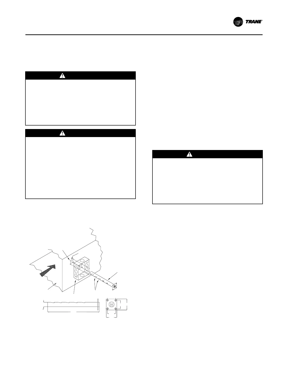
Install sensor in a turbulent free area of discharge air
duct where it will provide accurate supply air sensing
figure below for installation and sensor dimensions.
Figure 52. Discharge air sensor assembly
Mounting Holes
Insertion Hole
7/8” Dia.
VAV Discharge
Air Sensor
Airstream
Discharge Duct
Junction Box
Air Inlet Holes
1-3/4”
1-3/16”
1-3/16”
1-3/4”
13-5/8”
Sensor Dimensions
7/8”
The sensor serves two functions:
• Sends supply air temperature data to Discharge Air
Controller as an analog input, to control the
economizer (if applicable) and cycling of
compressors
• Low limit sensor for system when supply air
temperature reaches too high a delta T between
actual supply air temperature and supply air
temperature setpoint.
Before installing any connecting wiring, see drawings
in Dimensions and Weights chapter for electrical
access locations. Wire sensor per field connection
diagram, numbers 2307-9122 (for 20-60) and 2307-9144
(for 80-120). Shielded cable (Belden 8760 or equivalent)
must be used when wiring sensor to the terminal board
inside unit control panel.
Connect shielded cable to appropriate terminals on
terminal board (7TB7), in control panel.
Ground shield (at unit only) using ground screw in
customer 24 volt connection area as shown in field
connection diagram.
Suction Line Thermostat
WWAARRNNIINNGG
HHaazzaarrddoouuss VVoollttaaggee!!
FFaaiilluurree ttoo ddiissccoonnnneecctt ppoowweerr bbeeffoorree sseerrvviicciinngg ccoouulldd
rreessuulltt iinn ddeeaatthh oorr sseerriioouuss iinnjjuurryy..
DDiissccoonnnneecctt aallll eelleeccttrriicc ppoowweerr,, iinncclluuddiinngg rreemmoottee
ddiissccoonnnneeccttss bbeeffoorree sseerrvviicciinngg.. FFoollllooww pprrooppeerr
lloocckkoouutt//ttaaggoouutt pprroocceedduurreess ttoo eennssuurree tthhee ppoowweerr
ccaann nnoott bbee iinnaaddvveerrtteennttllyy eenneerrggiizzeedd.. VVeerriiffyy tthhaatt nnoo
ppoowweerr iiss pprreesseenntt wwiitthh aa vvoollttmmeetteerr..
Each unit ordered with variable air volume controls
(digit 9 in the model number) is shipped with a suction
line thermostat (6S63) that must be field installed.
Locate the thermostat close to the expansion valve
bulb on a slightly flattened portion of the suction line.
The thermostat must be securely fastened to the
suction line and a field provided thermoconductive
grease must be applied to the area to ensure good heat
transfer.
Before installing any connecting wiring, see drawings
in Dimensions and Weights chapter for electrical
access locations. Wire suction line thermostat per field
connection diagram, numbers 2307-9122 (for 20-60)
and 2307-9144 (for 80-120). See Table 22, p. 68 (AC
Conductors) for wiring specifications.
Insulate the suction line, where the thermostat is
mounted, to isolate it from the surrounding air.
IInnssttaallllaattiioonn EElleeccttrriiccaall