SS-SVX11K-EN
81
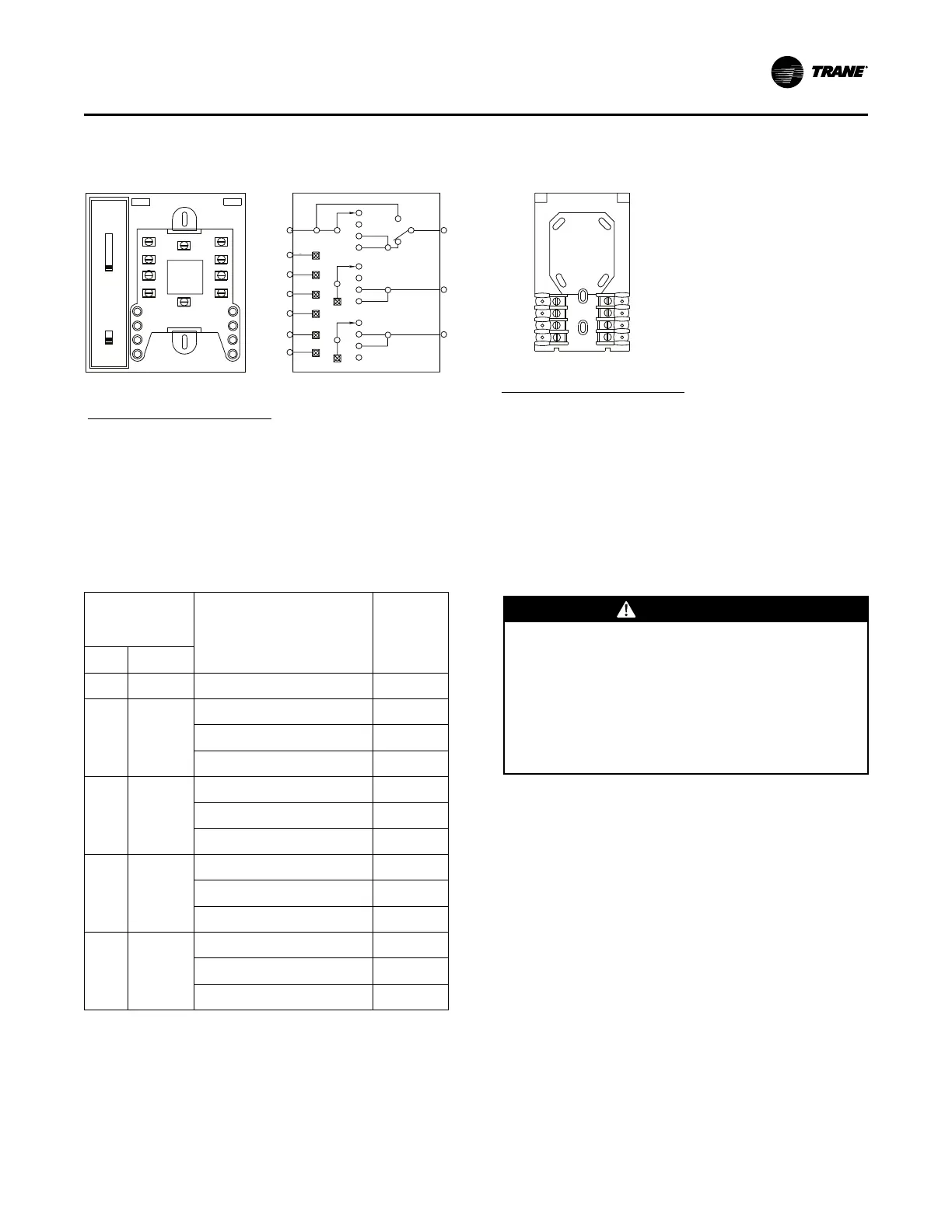
Figure 55. Q667 switching subbase & T7067 thermostat terminal identification
Switching Subbase
(Honeywell Q667)
Electronic Thermostat
(Honeywell T7067)
Terminal Layout Internal Wiring Schematic
1 = Common (- DC) and
Night Setback/Setup Input
2 = +20 VDC Input
3 = Duct Sensor Input
4 = COOL Signal Output
5 = HEAT Signal Output
6 = Heating Setback
7 = Not Used
8 = Night Setup of Cooling
Setpoint
9 = Fan Switching
10 = Fan Switching
Wiring Terminal Identification:
1 = Common (- DC) and
Night Setback/Setup Input
2 = +20 VDC Input
3 = Duct Sensor Input
4 = COOL Signal Output
5 = HEAT Signal Output
6 = Heating Setback
7 = Not Used
8 = Night Setup of Cooling
Setpoint
Wiring Terminal Identification:
RAUC\Thermostat Terminal ID
System
7
6
5
4
1
2
3
8
7
6
9
4
1
2
3
8
10
5
OFF
HEAT
AUTO
COOL
OFF
HEAT
AUTO
COOL
OFF
HEAT
COOL
AUTO
ON
FAN
AUTO
System
Fan
AUTO
ON
COOL
AUTO
HEAT
ON
7
6
9
4
1
2
3
8
10
5
Table 26. (Q667) switching subbase
Subbase
Switch
Positions
Check Continuity
between These Terminal
Pairs
Circuit
should
beFan
System
ON
N/A
9 (Subbase) & 10 (Subbase)
Closed
AU-
TO
OFF
9 (Subbase) & 10 (Subbase) Open
5 (Subbase) & 5 (T’stat) Open
4 (Subbase) & 4(T’Stat) Open
AU-
TO
HEAT
9 (Subbase) & 10 (Subbase) Open
5 (Subbase) & 5 (T’stat)
Closed
4 (Subbase) & 4(T’Stat) Open
AU-
TO
AUTO
9 (Subbase) & 10 (Subbase)
Closed
5 (Subbase) & 5 (T’stat)
Closed
4 (Subbase) & 4(T’Stat)
Closed
AU-
TO
COOL
9 (Subbase) & 10 (Subbase)
Closed
5 (Subbase) & 5 (T’stat) Open
4 (Subbase) & 4(T’Stat)
Closed
Thermostat Checkout
Once the subbase is mounted, before connecting any
wiring, use an ohm meter and complete the continuity
checks listed in .
Thermostat Wiring
WWAARRNNIINNGG
HHaazzaarrddoouuss VVoollttaaggee!!
FFaaiilluurree ttoo ddiissccoonnnneecctt ppoowweerr bbeeffoorree sseerrvviicciinngg ccoouulldd
rreessuulltt iinn ddeeaatthh oorr sseerriioouuss iinnjjuurryy..
DDiissccoonnnneecctt aallll eelleeccttrriicc ppoowweerr,, iinncclluuddiinngg rreemmoottee
ddiissccoonnnneeccttss bbeeffoorree sseerrvviicciinngg.. FFoollllooww pprrooppeerr
lloocckkoouutt//ttaaggoouutt pprroocceedduurreess ttoo eennssuurree tthhee ppoowweerr
ccaann nnoott bbee iinnaaddvveerrtteennttllyy eenneerrggiizzeedd.. VVeerriiffyy tthhaatt nnoo
ppoowweerr iiss pprreesseenntt wwiitthh aa vvoollttmmeetteerr..
Before installing any connecting wiring, see drawings
in the Dimensions and Weights chapter for the
electrical access locations provided on the unit. Wire
the thermostat in accordance with field connection
diagram, numbers 2307-9122 (for 20 to 60 ton units)
and 2307-9144 (for 80 to 120 ton units).
Discharge Air Sensor (Honeywell 6RT1)
A discharge air sensor ships with each unit when the
constant volume control option is ordered. The sensor
should be installed in a turbulent free area of the
discharge air duct at a location that will provide
accurate supply air sensing. Refer to the illustration in
Figure 52, p. 77 for installation and sensor dimensional
information.
IInnssttaallllaattiioonn EElleeccttrriiccaall