70
S9V2-VS-SVX001-1C-EN
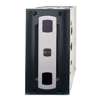
12. Remove the pressure switch bracket assembly.
13. Remove the screw that holds PS2, rotate 90 degrees
clockwise, and reattach.
14. Reattach the pressure switch bracket assembly.
NNoottee:: Illustration below shows the PS2 pressure switch
in the final rotated position.
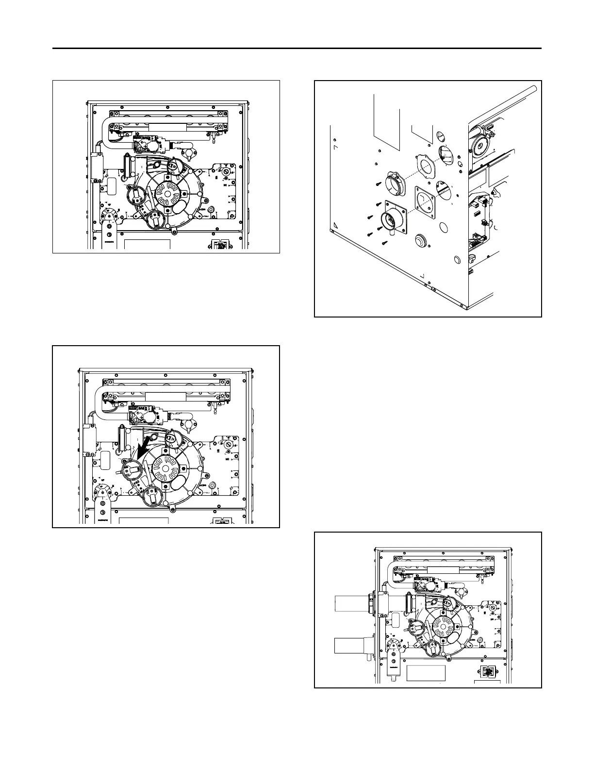
15. Attach the vent outlet gasket to the vent outlet.
16. Install vent outlet to top of cabinet using 2 screws
supplied in the dock pack.
17. Install vent inlet gasket and vent inlet using 4
screws supplied in the dock pack.
18. Install the grommet for the condensate drain tube.
The drain may be located on either side of the
cabinet.
19. Slide PVC through vent outlet adaptor and insert
into inducer outlet.
20. Twist to insure PVC is fully inserted.
21. Tighten the two clamps.
22. Install the combustion air inlet pipe.
NNoottee:: The vent outlet adapter is used for strain relief
against the weight of the venting. The clamp
should be tightened after the internal connection
is made.
NNoottee:: If required, transition to larger venting within 2'
of the cabinet. An 2" x 3" offset coupling is
required if the transition is made in a horizontal
plane. Use coupling CPL01544 (Canadian
applications may use BAYREDUCE to meet ULC-
S636 requirements.) See Horizontal Venting
section for proper orientation of 2” x 3” offset
coupling.
23. Connect PS2 tubing to switch and sensing location.
FFuurrnnaaccee CCoommbbuussttiioonn AAiirr EExxhhaauusstt OOppttiioonnss