RLC-SVX19G-GB
43
11UNT-PRC002-GB
Sound power levels
Discharge
Measurement conditions:
Measurements taken in a room adjacent to the room containing the FWD, at the outlet of the rectangular duct (1.5 m
long) fixed to its discharge opening.
Fan Power level in dB(A), per Hz frequency band Overall power
Unit speed 125 250 500 1000 2000 4000 8000 dB(A)
1 55 50 42 37 37 31 30 46
FWD 08 2 57 54 47 40 30 38 40 50
3 58 57 50 42 32 40 43 53
1 57 51 45 42 34 33 28 48
FWD 10 2 58 54 48 45 38 39 35 51
3 60 58 50 48 40 42 39 54
1 57 51 45 42 34 33 28 48
FWD 12 2 58 54 48 45 38 39 35 51
3 60 58 50 48 40 42 39 54
1 56 62 50 48 39 38 36 56
FWD 14 2 61 66 55 53 47 46 45 60
3 63 69 58 56 50 50 49 63
1 57 63 51 49 40 39 37 57
FWD 20 2 61 66 55 53 47 46 45 60
3 63 69 58 56 50 50 49 63
Intake
Measurement conditions:
Measurements taken at the horizontal air intake.
Fan Power level in dB(A), per Hz frequency band Overall power
Unit speed 125 250 500 1000 2000 4000 8000 dB(A)
1 56 55 55 53 46 45 42 57
FWD 08 2 63 62 60 60 53 53 53 64
3 66 65 63 62 56 55 57 67
1 62 58 55 58 51 48 44 61
FWD 10 2 66 63 60 62 56 55 52 66
3 70 67 63 65 59 59 57 69
1 62 58 55 58 51 48 44 61
FWD 12 2 66 63 60 62 56 55 52 66
3 70 67 63 65 59 59 57 69
1 66 65 65 65 57 50 46 68
FWD 14 2 73 72 69 71 64 59 57 74
3 78 76 73 75 69 64 63 78
1 68 72 64 64 56 52 50 69
FWD 20 2 76 76 68 71 65 61 61 75
3 78 79 71 74 69 66 66 78
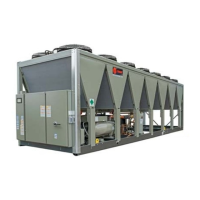
Table 10b – General data RTAF 090-225 & 101 High Seasonal Efficiency - Extra Low Noise - R1234 ze
RTAF RTAF RTAF RTAF RTAF RTAF RTAF RTAF RTAF RTAF RTAF
090 100 110 120 130 145 155 185 200 225 101 (10)
HSE XLN HSE XLN HSE XLN HSE XLN HSE XLN HSE XLN HSE XLN HSE XLN HSE XLN HSE XLN HSE XLN
Cooling Capacity (1) (kW) 326 357 393 426 460 510 554 614 725 841 781
Unit electrical data (2) (3) (4)
Maximum Power input in cooling (kW) 169 184 198 222 245 270 292 296 338 385 378
Unit rated amps (Max compressor+fan+control) (A) 259 281 302 338 374 412 445 451 516 587 575
Unit start up amps starting Amps of the
larges compr+RLA of 2nd compr+RLA of all
fans+control)
(A) 259 281 302 338 374 412 445 451 516 587 575
Displacement Power Factor (DPF) 0.95 0.95 0.95 0.95 0.95 0.95 0.95 0.95 0.95 0.95 0.95
Max power cable cross section mm
²
1*240 1*240 1*240 1*240 1*240 2*300 2*300 2*300 2*300 2*300 2*300
Disconnect switch size (A) 400 400 500 500 500 630 630 630 800 800 800
Compressor
Quantity # 2 2 2 2 2 2 2 2 2 2 2
Type Screw Screw Screw Screw Screw Screw Screw Screw Screw Screw Screw
Model (9) 45/45 55/45 55/55 65/55 65/65 78/65 78/78 78/78 78/78 78/78 78/78
Max Compr Power input (Circuit 1 / Circuit 2) kW 74/74 89/74 89/89 112/89 112/112 134/112 134/134 134/134 155/155 179/179 179/179
Max Amps Circuit1 / Circuit 2 (3) (5) (A) 113/113 135/113 135/135 171/135 171/171 203/171 203/203 203/203 236/236 271/271 271/271
Start up Amps Circuit1 / Circuit 2 (3)(5) (A) 113/113 135/113 135/135 171/135 171/171 203/171 203/203 203/203 236/236 271/271 271/271
Motor RPM (rpm) 3000 3000 3000 3000 3000 3000 3000 3000 3600 4200 4200
Oil sump heater Circuit1 / Circuit 2 (W) 150/150
Evaporator
Quantity # 1 1 1 1 1 1 1 1 1 1 1
Type Flooded shell and tube heat exchanger
Evaporator model 115B 115A 115A 165C 165B 200C 200C 200B 250B 250B 165B
Evaporator Water Content volume (l) 51 58 58 64 74 89 89 99 118 118 74
Antifreeze Heater (W) 1640 1640 1640 1640 1640 1640 1640 2040 2040 2040 1640
Two pass evaporator
Evap. Water Flow rate - Minimum (6) (l/s) 8.0 9.4 9.4 11.1 11.6 13.0 13.0 14.2 17.9 17.9 11.6
Evap. Water Flow rate - Maximum (l/s) 29.6 34.7 34.7 41.2 43.1 48.0 48.0 52.6 66.5 66.5 43.1
Nominal water connection size (Grooved
coupling)
(in) - (mm) 4" - 100 4" - 100 4" - 100 5" - 125 5" - 125 6" - 150 6" - 150 6" - 150 6" - 150 6" - 150 5" - 125
Two pass evaporator with turbulator
Evap. Water Flow rate - Minimum (6) (l/s) 6.6 7.8 7.8 9.3 9.7 10.8 10.8 11.8 14.9 14.9 9.7
Evap. Water Flow rate - Maximum (l/s) 26.6 31.2 31.2 37.0 38.7 43.1 43.1 47.2 59.7 59.7 38.7
Nominal water connection size (Grooved
coupling)
(in) - (mm) 4" - 100 4" - 100 4" - 100 5" - 125 5" - 125 6" - 150 6" - 150 6" - 150 6" - 150 6" - 150 5" - 125
Hydraulic Module Components
Standard head pressure pump option (twin pumps)
Available Head Pressure (1) (kPa) 126 111 107 136 121 160 151 131 89 93 N/A
Max. Motor Power (kW) 5.5 5.5 5.5 5.5 7.5 7.5 11.0 11.0 11.0 11.0 11.0
Max Amps (A) 11.0 11.0 11.0 11.0 14.4 14.4 20.8 20.8 20.8 20.8 20.8
High head pressure pump option (twin pumps)
Available Head Pressure (1) (kPa)
246 243 227 222 212 237 226 218 244 197 209
Max. Motor Power (kW) 11.0 11.0 11.0 11.0 11.0 15.0 15.0 15.0 18.5 18.5 18.5
Max Amps (A) 20.8 20.8 20.8 20.8 20.8 28.0 28.0 28.0 34.5 34.5 34.5
Expansion Tank Volume (l) 80 80 80 80 80 80 80 80 80 80 80
Max User water loop Volume for factory mounted
expansion tank (1)
(l) 6000 6000 6000 6000 6000 6000 6000 6000 6000 6000 6000
Max. Water-side Operating Pressure without
pump package
(kPa) 1000 1000 1000 1000 1000 1000 1000 1000 1000 1000 1000
Max. Water-side Operating Pressure with pump
package
(kPa) 450 450 450 450 450 450 450 450 450 450 450
Antifreeze Heater with pump package (W) 2360 2360 2360 2360 2360 2360 2360 2760 2760 2760 2360
Condenser
Type
Quantity # 5/5 5/5 5/5 5/5 5/5 6/6 6/6 7/7 7/7 7/7 5/5
Face area per coil (m²) 2.4 2.4 2.4 2.4 2.4 2.4 2.4 2.4 2.4 2.4 2.4
Condenser Fan (nominal conditions)
Quantity # 5/5 5/5 5/5 5/5 5/5 6/6 6/6 7/7 7/7 7/7 5/5
Diameter (mm) 800 800 800 800 800 800 800 800 800 800 800
General Data

 Loading...


