26
PKG-SVX029A-EN
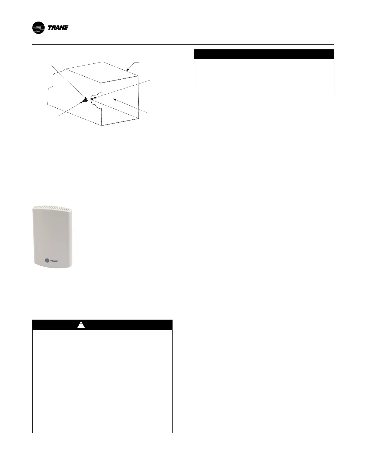
Figure 12. Static pressure sensor installation
Static Pressure Head Assembly
Note: Place Sensor Inlet Perpendicular to Airflow
Airflow
Connector for 1/4-inch Tubing
Connector for
1/4-inch Tubing
Duct
Zone Sensor Option used for
Discharge Air Reset by Space
Temperature
Zone Temperature Sensor, BAYSENS077
(Optional Item)
Figure 13. Zone temperature sensor
This zone sensor includes an internal thermistor and
should be mounted in the zone, Model Number Digit 31=1.
This sensor is available for use with all zone sensor options
to provide remote sensing capabilities.
Zone Sensor Installation
WARNING
Hazardous Voltage w/Capacitors!
Failure to disconnect power and discharge capacitors
before servicing could result in death or serious
injury.
Disconnect all electric power, including remote
disconnects and discharge all motor start/run
capacitors before servicing. Follow proper lockout/
tagout procedures to ensure the power cannot be
inadvertently energized. For variable frequency drives
or other energy storing components provided by
Trane or others, refer to the appropriate
manufacturer’s literature for allowable waiting periods
for discharge of capacitors. Verify with a CAT III or IV
voltmeter rated per NFPA 70E that all capacitors have
discharged.
NOTICE
Use Copper Conductors Only!
Failure to use copper conductors could result in
equipment damage as the equipment was not
designed or qualified to accept other types of
conductors.
Note: For additional information regarding the safe
discharge of capacitors, see Discharging Capacitors
in HVAC Systems Service Bulletin (PROD-SVB06*-
EN).
All sensor options ship in the main control panel and are
field installed. Programmable option installation
procedures.
Mounting Location
Mount the sensor on the wall in an area with good air
circulation at an average temperature. Avoid mounting
space temperature sensor is areas subject to the following
conditions:
• Drafts or dead spots behind doors or in corners
• Hot or cold air from ducts
• Radiant heat from the sun or appliances
• Concealed pipes and chimneys
• Unheated or non-cooled surfaces behind the sensor,
such as outside walls
• Airflows from adjacent zones or other units
To mount the sensors, remove the dust cover and mount
the base on a flat surface or 2-inch x 4-inch junction box.
Sensors ship with mounting screws.
Mounting the Subbase
Remove the zone sensor cover from subbase, and mount
subbase on the wall or on a 2-inch x 4-inch junction box.
Route wires through the wire access hole in the subbase.
See Figure 14, p. 27. Seal the hole in the wall behind the
subbase.
Notes:
• Guidelines for wire sizes and lengths are shown
in Table 9, p. 27. The total resistance of these
low voltage wires must not exceed 2.5 ohms
per conductor. Any resistance greater than 2.5
ohms may cause the control to malfunction due
to excessive voltage drop.
• Do not run low-voltage control wiring in same
conduit with high-voltage power wiring.
Wiring
1. Run wires between the unit control panel and the zone
sensor subbase. To determine the number of wires
required, refer to the unit wiring diagrams.
2. Connect the wiring to the appropriate terminals at the
unit control panel and at the zone sensor subbase. In
general, zone sensor connections to the unit use the
Installation - Electrical