20
PKG-SVX029A-EN
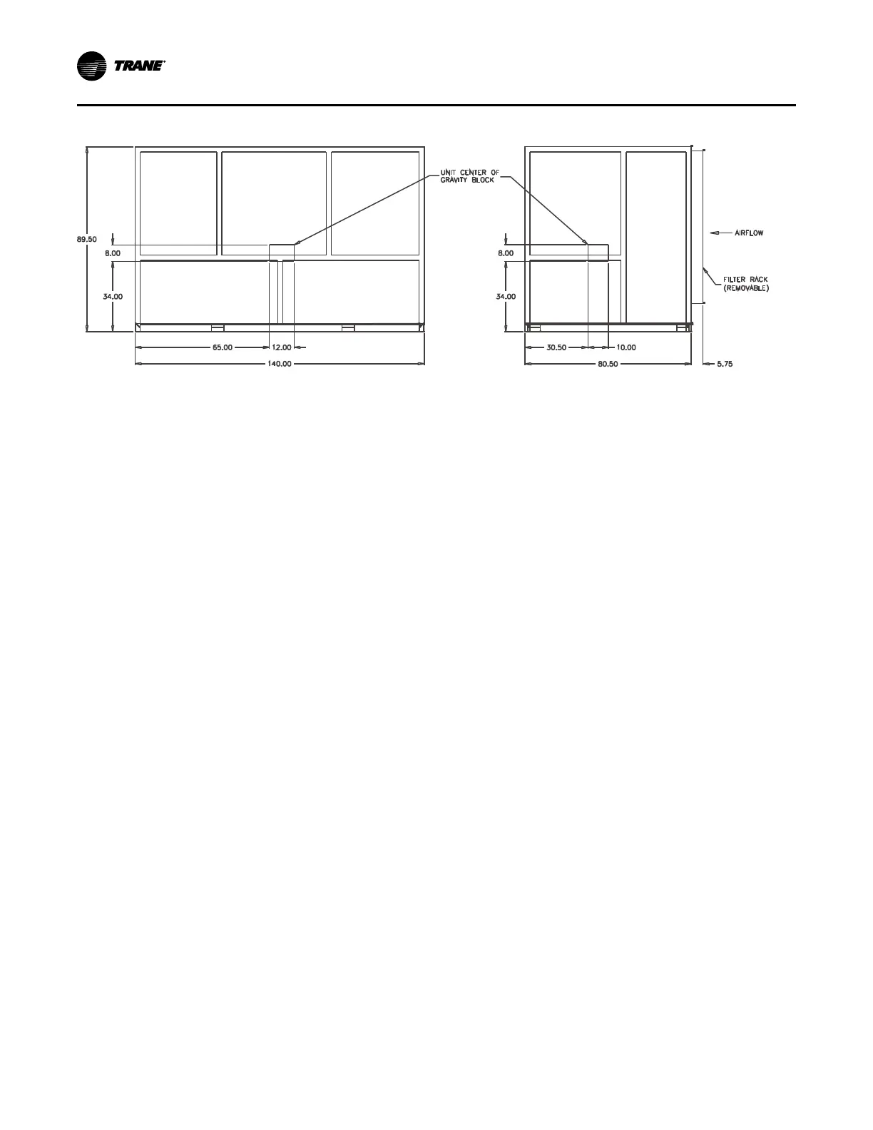
Figure 8. Gravity block location and dimensions for 90 to 110 ton units
Installation Preparation
Before installing the unit, perform the following procedures
to confirm proper unit operation.
1. Position the unit and pallet in its final location.
2. Test lift the unit to determine exact unit balance and
stability before hoisting it to the installation location.
See “Unit Handling,” p. 19 for proper rigging
procedures and cautions.
3. Remove the protective shipping covers from the unit.
Unit Vibration Isolator Option
Important: Vibration isolation is not necessary for the unit
since the factory internally isolates the fan and
compressor, thus creating double isolation.
Trane strongly recommends consulting a
vibration specialist when considering double
isolation. Trane does not recommend double-
isolation.
Unit Isolator Installation
Procedure
Use the following procedure to install isolators:
1. Position the isolators under the unit base referring to
the isolator placement sheet that ships with the unit
isolators. Lift one end of the unit at a time to position
the isolators.
2. Shim as required to level the unit. It must be less than
1/8-inch per foot difference.
Note: The unit is equipped with a positively sloped drain
pan to help indoor air quality (IAQ) and does not
require one corner of the unit to be pitched.
Duct Connections
Return air enters the rear of the unit and conditioned supply
air discharges through the top.
Notes:
• Attach supply air ductwork directly to the unit
top panel, around the fan discharge opening. A
duct collar is not provided.
• Units equipped with flexible horizontal
discharge plenum option may include a duct
collar when holes are factory cut.
Install all air ducts according to the National Fire Protection
Association standards for the Installation of Air
Conditioning and Ventilation Systems other than
Residence Type (NFPA 90A) and Residence Type Warm
Air Heating and Air Conditioning Systems (NFPA 90B).
Make duct connections to the unit with a flexible material
such as heavy canvas. If a fire hazard exists, Trane
recommends using Flexweave 1000, type FW30 or
equivalent canvas. Use 3 inches for return duct and 3
inches for discharge duct. Keep material loose to absorb
fan vibration.
• If using return ductwork to the unit, secure it with 3
inches of flexible duct connector.
• Extend discharge duct upward without change in size
or direction for at least three fan diameters.
• Use 3-inch flexible duct connection on discharge
ductwork.
Note: Compressors and fan assembly are internally
isolated. External isolation devices (spring mounting
isolators) are at discretion of a vibration specialist
consulted by building or HVAC system designer.
Run the ductwork straight from the opening for a minimum
of three fan diameters. See Figure 9, p. 21. Extend
remaining ductwork as far as possible without changing
size or direction. Do not make abrupt turns or transitions
near the unit due to increased noise and excessive static
losses. Use elbows with splitters or turning vanes to
minimize static losses.
Poorly constructed turning vanes may cause airflow
generated noise. Align the fan outlet properly with the
ductwork to decrease noise levels in the duct and to
increase fan performance. To complete trunk ductwork to
the VAV terminal units, refer to the VAV box manuals for
Installation – Mechanical