Installation
20 CDUB-SVN002B-EN
Heat Recovery/Aux COND Option
When heat recovery/Aux COND option is selected, a
DHVBI LLID (BRD04874) is required as 1A29, heat
recovery/Aux COND flow switch wiring, ref. ref. 50712795,
50712799, 50712802, 50712805 or 50712806 depend on
different unit. For details, see Table 3, p. 27.
Energy Meter Option Installation
The Trane energy meter provides instrument grade
accuracy power, volts and amps monitoring of Symbio
controls installations. It has 1% accuracy for measuring
both real power and energy and reactive power and
energy. All data measured by the meter is communicated
via Modbus to Symbio control system. Detail information
refer IOM BAS-SVN224*-EN. Please note this option isn’t
applied for HDWA and CVHM production.
The meter is connected to line voltage of up
to
480 volts
and should be mounted within the starter cabinet. It is
provided with a mounting bracket that can either be
mounted on DIN rail or directly to cabinet wall. is
mountable using the provided bracket.
The meter is connected to Modbus communications and is
self-p
owered by the unit voltage potential inputs. Review
meter literature for setup and operation details.
Modbus communications is by shielded 14 – 26 AWG
cabl
e from meter to Symbio module. Please install 120
OHM resistors at first and last modules on Modbus daisy
chain.
Figure 29. Schematic of heat r
ecovery/AUX cond option
1A29 DUAL HIGH VOLTAGE BINARY INPUT
4
4
1
RED
1
J1
J11
J2
2
1
1
2
J3
2U
1X1-7
TO 1X1-5
1X1-15
TO 1X1-12
65A
5S16
SECONDARY
5S15
PRIMARY
64A
1A28 DUAL ANALOG I/O
OPTIONAL
INPUT 1
OUTPUT 1
2
1
GND
INPUT 2
OUTPUT 2
GND
4
3
J2
5
6
HEAT RECOVERY
5B3 CUSTOMER PROVIDE
4-20mA
FLOW
METER
24VDC
1A2 J3-1
0V
1A2 J3-2
OUTPUT
SIGNAL
AUX COND FLOW METER
IPC BUS
AND WATER FLOW DETECTION
AUX COND FLOW METER
OPTIONAL
OPTIONALREQUIRED
5AE 65A
IPC BUS
WATER PRESSURE
AUX COND LEAVING
HEAT RECOVERY
TRANSDUCER
OPTIONAL
WATER PRESSURE
AUX COND ENTERING
HEAT RECOVERY
TRANSDUCER
OPTIONAL
4
4
RED
J11
1
J1
1
AUX COND FLOW METER
CUSTOMER PROVIDE 4-20MA INPUT
AUX COND WATER FLOW DETECTION
-
Pg
+
SIG
4B5
-
Pg
+
SIG
4B6
3
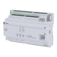
Figure 30. Energy meter
Figure 31. Rogowski CTs
Figure 32. Mount the energy meter with strap tunnel
on the rail
Figure 33. Shielded cable
–
S
+
Shielded Wire
120 terminators on the first/last devices of daisy
chain
Ω

 Loading...