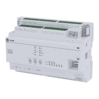
The Trane Symbio 700 Controller is a factory-installed, pre-programmed digital control system designed for heating, ventilating, and air-conditioning (HVAC) equipment. It provides comprehensive control and protection for HVAC systems, specifically tailored for use with Trane's Odyssey cooling and heat pump systems. The Symbio 700 system comprises a main controller and can be expanded with up to four optional modules, depending on the specific functional requirements of the equipment. These option modules enhance the system's capabilities, allowing for more complex operations and configurations.
The controller is designed with an emphasis on flexibility and connectivity. It features an open architecture, making its software readily available for both configuration and troubleshooting. This design choice simplifies the process of managing and maintaining the HVAC system. The software is also field-upgradable, ensuring that the controller can be updated with the latest features and improvements without requiring a complete hardware replacement. This upgradability helps to future-proof the system and extend its operational lifespan.
A key aspect of the Symbio 700 is its integration with mobile service technology. This empowers users, particularly service technicians, to interact with the controller using a mobile device. This mobile-centric approach allows for advanced configuration, setup, status updates, alarm management, and various service capabilities directly from a smartphone or tablet via a Bluetooth connection. The controller supports Bluetooth Low Energy (BLE) version 4.2 and higher, enabling a secure and efficient wireless connection. To prevent conflicts, only one mobile device connection is allowed at a time. In cases of accidental or purposeful disconnections, a timer is implemented to prevent the controller from being locked by a user who did not properly disconnect, ensuring system accessibility.
The Symbio 700 offers a full suite of communication options for Building Automation System (BAS) integration. This includes support for BACnet® (ANSI/ASHRAE Standard 135-2016) via MS/TP, IP, or ZigBee® (Air-Fi® Wireless), as well as LonTalk™™. These protocols enable seamless communication with most existing building automation systems, allowing the Symbio 700 to be integrated into larger, more complex building management infrastructures. For advanced custom sequences and side control functionalities, the controller also supports optional TGP2 and XM features, which typically require Trane Tracer TU software. The "Connected" feature provides optional remote access and monitoring capabilities, which can significantly aid in troubleshooting by allowing technicians to diagnose issues without needing to be physically present at the site.
The user interface of the Symbio 700 controller is designed for ease of use, featuring a 2x16 backlit LCD display located in the middle of the unit. This onboard user interface includes a Bluetooth pair button, facilitating the connection with the mobile service tool. The interface allows users to navigate through menus and submenus using up/down and left/right buttons. An "Enter" button is used to drill down into menu components and confirm data changes. When editing data, the least significant digit flashes with a cursor, and users can scroll left and right to select editable digits. Data changes are not propagated until the "Enter" button is tapped. A "Home" button allows users to exit all submenus and return to the main Home screen, while a "Cancel" button returns to the previous menu level. The Bluetooth button initiates the device pairing sequence.
The controller's functionality is categorized into two model options: Standard Configuration and Advanced Configuration. The Standard Configuration provides basic troubleshooting capabilities through the onboard user interface and access to the Symbio Service and Installation mobile app. It displays the last five events in the event log (accessible via the mobile service tool), shows the most current active alarms with the highest priority (also accessible via the mobile service tool), and does not allow for trend exports or onboard UI access to these features. Communication protocols are not supported in the standard configuration.
The Advanced Configuration, on the other hand, introduces additional troubleshooting tools and enhanced BAS interface capabilities. With this option, the event log is unrestricted and accessible via the mobile service tool, though still unavailable on the onboard UI. Active alarms are unrestricted and viewable on the onboard UI. Trend exports are unrestricted and accessible via the mobile service tool, but not on the onboard UI. Crucially, the Advanced Configuration supports BACnet MS/TP, BACnet Air-Fi, BACnet IP, and LonTalk communication protocols, as well as TGP2, providing extensive integration possibilities. Upgrading from Standard to Advanced Functionality requires purchasing a new Symbio 700 controller with the Advanced Functionality and installing it on the equipment.
Maintenance features are supported through various menu options. The "Status" menu allows users to view the unit's operation, active setpoint values, and the status of system components such as indoor and refrigeration systems. The "Settings" menu enables users to change parameters like arbitration method requests, emergency override BAS, unit stop commands, and information related to supply fan, filter runtime hours, compressor, and refrigeration circuits. The "Service" menu provides access to diagnostics, allowing users to reset active diagnostics. It also includes a "Test Mode" for setting the unit into a service test, a "Statistic Reset" option to clear component statistic data, and "Options Modules" to display configuration, communication status, and firmware versions of installed modules. The "Modbus" option shows the communication status of Modbus devices.
The "Alarms" menu provides a list of active alarms, with the newest alarm listed first, displaying the point name and assigned severity. The "Utilities" menu offers information about the controller, including software versions of Symbio modules, a read-only list of the current unit configuration, and an option to edit configuration settings. Users can also change display units and scroll speed, and view/edit the current date, time, and time zone. A "Service Pin" request is also available.
The controller's LEDs provide visual indications of its operational status. For instance, binary output LEDs (1-2, 4-6, 15-22) are solid ON when the output is active and OFF when inactive. LED 3 indicates Bluetooth status: OFF means the radio is unavailable, ON means an active connection is in process, and BLINKING means the controller is waiting for a connection. LEDs 7 and 8 indicate link connection and activity. LED 10, the Status LED, is SOLID GREEN for normal operation, OFF when not powered or in alarm, and BLINKING RED for abnormal states. Modbus and IMC link LEDs (11-14) blink green for data transmission and yellow for data reception. BACnet MS/TP link LEDs (23-24) also blink yellow for received data and green for transmitted data.
The Symbio 700 also supports conventional thermostats and zone sensors. For thermostats, the J21 terminal accepts signals for 24VAC power, cooling stages (Y1, Y2), supply fan (G), heating stages (W1, W2), and emergency heat (X2). For heat pump-only systems, it includes an "O" signal for the switchover valve. The controller processes these signals, ensuring compressor protection and reliability functions like HPC, LPC, and minimum On/Off timers. It also handles simultaneous heating and cooling calls by ignoring them and ensures the fan runs with any heating or cooling call. A delay is implemented when switching between heating and cooling modes. For zone sensors, a 10k ohm resistance type 2 thermistor can be wired to terminals J19-1 and J19-2 for space temperature input. For larger zones, multiple 10K ohm thermistors can be wired in parallel to provide an average input, ensuring a more accurate representation of the zone temperature.