EasyManua.ls Logo

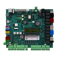
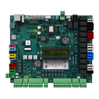
Trane Symbio 700 - Factory Connections P20-SW3 and Field Diagram

Trane Symbio 700
20 pages
To Next Page IconTo Next Page
To Previous Page IconTo Previous Page
Loading...
14
BAS-SVU054A-EN
Table 4. Symbio 700 factory connections (continued)
Factory Connection
Function Pin #
Signal
P20 Circuit 2 LPC
1 24Vac Out
2
Circuit 2 LPC Input
P21
Spare
1 24Vac Out
2
Spare
J1 Ethernet
J2 USB Host
a
J3 IMC Communication
1 24V DC Power out
2 GND
3 IMC +
4 IMC -
J4
Input Power
1
24VAC In/Out
2 GND
J5
Input Power
1
24VAC In/Out
2 GND
J6
Phase Monitor Input
1 24VAC Out
2
Phase Monitor Input
3 GND
SW1 BACnet Address NA
SW2 BACnet Address NA
SW3 BACnet Address NA
(a) USB HOST not intended to charge mobile phones
Figure 4. Symbio 700 field connections
TTeecchhnniiccaall SSppeecciiffiiccaattiioonnss

Other manuals for Trane Symbio 700

Related product manuals