EasyManua.ls Logo

Trane Symbio 500 User Manual

Trane Symbio 500
56 pages
To Next Page IconTo Next Page
Page #1 background imageLoading...
Page #1 background image
SAFETY WARNING
Only qualified personnel should install and service the equipment. The installation, starting up, and servicing of heating, ventilating, and air-conditioning equipment
can be hazardous and requires specific knowledge and training. Improperly installed, adjusted or altered equipment by an unqualified person could result in death or
serious injury. When working on the equipment, observe all precautions in the literature and on the tags, stickers, and labels that are attached to the equipment.
April 2023
BAS-SVX090B-EN
Installation, Operation, and Maintenance
Symbio™ 500 Programmable
Controller
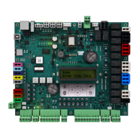
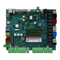
BMSY500AAA0100011 Symbio 500 Programmable Controller
BMSY500UAA0100011 Symbio 500 Programmable Controller, made in the USA
BMSY500ABA0100011 Symbio 500 Rooftop / Heat Pump Controller (RTU/HP)
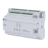
Table of Contents

Questions and Answers:

Trane Symbio 500 Specifications

General IconGeneral
Communication ProtocolBACnet, Modbus
TypeController
DisplayColor touchscreen
ConnectivityEthernet
FeaturesEnergy management, scheduling
Supply Voltage24 VAC
Operating Temperature-20°C to 50°C
Humidity Rangenon-condensing
Memory8 GB
Weight1.5 lbs (0.68 kg)
Enclosure RatingIP20

Summary

Introduction

Warnings, Cautions, and Notices

Defines advisory types (WARNING, CAUTION, NOTICE) used in the manual.

Environmental and Refrigerant Practices

Covers environmental concerns and responsible refrigerant handling guidelines.

Electrical Safety and Grounding

Highlights critical warnings for field wiring and grounding.

Safety and Policy

Personal Protective Equipment (PPE)

Details essential PPE for safe installation and servicing of equipment.

EHS Policy Compliance

Mandates adherence to Environmental, Health, and Safety policies.

Revision History

General Information

Specifications

Details storage/operating conditions, power, agency compliance, and ratings.

Sensors Supported

Lists types of sensors compatible with the Symbio 500 controller.

Device Connections

Device Connections

Describes various input/output connection types, quantities, ranges, and notes.

Expansion Modules

Explains the capability to expand points using expansion modules.

Accessories and User Interface

Required Tools

Lists required tools for installation and testing.

Symbio User Interface (UI)

Covers the web-based UI for installation, integration, and service tasks.

Connecting to Symbio UI

Provides steps for connecting a laptop to access the Symbio UI.

Mounting and Clearances

Clearances

Provides required clearances for controller installation.

DIN Rail Mounting

Details instructions and best practices for mounting on a DIN rail.

Wiring Overview

General Instructions

Introduces wiring, compliance with codes, and basic connection methods.

BACnet Communication

BACnet MS/TP Communication Link

Details BACnet MS/TP wiring and performance best practices.

BACnet/IP and Air-Fi Wireless

Covers BACnet/IP over Ethernet and Air-Fi wireless communication.

Wiring Guidelines for BACnet MS/TP

Provides specific guidelines for wired BACnet MS/TP installations.

Wiring Best Practices

Wiring Best Practices

Provides guidelines for proper network communication wiring.

Setting Up on BACnet Link

Details steps for setting up the controller on a BACnet network link.

Address Configuration

Setting the Address

Explains how to set the MAC and BACnet Device IDs using rotary dials.

BACnet Networks without Tracer SC+

Describes Device ID assignment for networks without a Tracer SC+ controller.

BACnet Networks with Tracer SC+

BACnet Networks with Tracer SC+

Details Device ID assignment for networks with a Tracer SC+ controller.

Ethernet Ports

Describes the two Ethernet ports and their functionality for BACnet/IP.

Power Supply

Hazardous Voltage Warning

Critical warning about disconnecting power before servicing.

Ground Connection Requirements

Emphasizes the need for proper grounding of the 24 Vac transformer.

Equipment Damage Notice

Warns about potential damage from sharing 24 Vac power.

Power Supply Details

Transformer Recommendations

Provides requirements for AC and DC power transformers.

Wiring Recommendations

Offers guidelines for installing the power supply circuit.

Connecting Wires

Instructions for disconnecting power and grounding controller terminals.

Power On and Pre-Power Checks

Power On Check

Details the sequence to verify controller power and boot status.

Pre-power Checks

Lists essential checks before connecting any inputs/outputs.

Input/Output Wiring and Checks

Point Check Diagram

Shows diagrams and methods to check points before power application.

Resistive and Voltage Inputs

Details checkout procedures for resistive and voltage input types.

Current Inputs

Explains checkout procedures for current input types.

Specific Input Wiring

0-20 mA Analog Inputs

Details checkout procedures for 0-20 mA analog inputs.

Binary Inputs, 24 Vac Detect

Explains checkout procedures for binary inputs detecting 24 Vac.

Binary Inputs Based on Analog Output

Covers checkout for binary inputs based on analog output connections.

Wiring Requirements and Power Budget

Wiring Requirements

Outlines maximum wire lengths and wiring guidelines.

Providing Low-voltage Power for I/Os

Explains how the controller provides low-voltage power to I/Os.

Calculating Power Consumption Rules

Provides guidelines for calculating power consumption and budgets.

Terminal Locations

Terminal Locations Overview

Illustrates the location of various I/O bus terminals and communication links.

Pressure Transducer Inputs

Details wiring for 3-wire pressure sensor transducers.

Binary Inputs

Explains monitoring fan status or alarm resets using binary inputs.

Analog Input Types

0-10 Vdc Analog Inputs

Details wiring for 0-10 Vdc analog inputs from sensors.

mA Analog Inputs

0-20 mA Analog Inputs

Details wiring for 0-20 mA analog inputs from sensors.

Variable Resistance Analog Inputs

Variable Resistance Analog Inputs

Explains wiring for analog inputs using variable resistance sensors.

Analog Outputs

Analog Outputs

Explains the two analog outputs for controlling actuators or secondary controllers.

Relay Outputs

Relay (Dry Contact/Binary Outputs)

Details wiring for three relay binary outputs used as powered outputs.

TRIAC Wiring

TRIAC Wiring

Explains wiring to TRIAC binary outputs for low/high side switching.

Operation

LED Locations

Identifies the location of LEDs on the front of the Symbio 500 controller.

LED Descriptions and Troubleshooting

Provides descriptions of LED activities and troubleshooting tips.

Marquee LED Status and Error Codes

Marquee LED Status and Error Codes

Explains the two-digit LED codes for status and error conditions.

Configuration and Maintenance Tasks

Task 1: Load Application Code

Details loading application code on a blank Symbio 500 controller.

Task 2: Choose Configuration Option

Explains selecting factory or custom configuration options.

Task 3: Specify Controller Settings

Covers configuring units, date/time, and baud rate.

Task 4: Setup Expansion Modules

Guides setting up and discovering XM30, XM32, XM70, XM90 expansion modules.

Configuration Tasks

Task 5: Specify Equipment Configuration

Details creating a factory or custom equipment configuration.

Task 6: Commission Hard-wired Points

Explains commissioning or testing points after download.

Task 7: Modify TGP2 Programs

Guides creating or editing TGP2 programs for equipment operation.

Task 8: Monitor Status

Covers viewing point, alarm, and controller status.

Backup and Restore

Task 9: Backup/Restore Files

Details uploading, backing up, and restoring configuration files and firmware.

Maintenance

Commissioning and Troubleshooting (Powered State)

Voltage Inputs

Details methods to check voltage inputs in a powered state.

Resistive Inputs

Details methods to check resistive inputs in a powered state.

Current Inputs

Details methods to check current inputs in a powered state.

Current Input Measurement

Current Inputs, Methods 1 or 2

Explains methods to check current inputs and their expected values.

Linear Current Input Measurement

Linear Current Input Measurement

Provides a chart for measuring voltage across linear current inputs.

Vac Measurement and Binary Inputs

24 Vac Measurement

Details how to measure the 24 Vac input power to the controller.

Binary Inputs, 24 Vac Detect

Explains methods to check binary inputs detecting 24 Vac.

Binary Input and Sensor Types

Binary Inputs, Based on Analog Output

Covers checkout for binary inputs based on analog output connections.

Open-collector Based Binary Sensors

Explains checking open-collector based binary sensors.

Analog Output Measurement

Voltage Analog Output

Details how to measure DC voltage for voltage analog outputs.

Current Analog Output, Methods 1 or 2

Explains methods to check current analog outputs.

TRIAC Output Switching

TRIAC High Side Switching

Details methods to check TRIAC high side switching outputs.

TRIAC Low Side Switching

TRIAC Low Side Switching

Details methods to check TRIAC low side switching outputs.

Ground Measurements

Ground Measurements

Explains methods to measure AC voltage for ground connections.

Resources

Related product manuals