50
BAS-SVX090B-EN
General Information and Checkout
Procedure Measurement
Expected Value
Method 1: Voltage across binary input
measured without reference to chassis
ground.
Measure AC voltage across the binary
input
Vac ≈ 24.0 V (state = OFF)
Vac ≈ 0.0 V (state = ON)
Method 2: Voltage across binary input
measured with reference to chassis
ground. Any connection with chassis
ground symbol can serve as a ground
reference for this method.
Measure DC voltage across the binary
input
Vac ≈ 0.0 V (state = ON)
Vac ≈ 24.0 V (state = OFF)
Binary Inputs, Based on Analog Output Connection
General Information Checkout Procedure Measurement
Expected Value
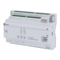
The Symbio 500 analog
output connections can be
configured as binary inputs.
This can be used only with
dry contact or open collector-
type sensors.
Step 1
Measure AC voltage across
the binary input
Vac ≈ 0.0 V
AC voltage will affect further
measurement
Step 2
Measure DC voltage across
the binary input
Vdc ≤ 2.0 V (state = ON)
Vfc ≤ 2.0 V (state = OFF)
Open-collector Based Binary Sensors
Measurement Procedure
Expected Value
Measure DC voltage across the binary input
Vdc ≤ 0.2 V (BJT = ON)
UI: Vdc ≈ 3.3 V (BJT = OFF)
AO: Vdc ≈ 22.0 V (BJT = ON)
Open-collector based binary sensors use a bipolar junction transistor (BJT; a three-terminal device in
which emitter-to-collector current is controlled by base current) as the switching device in place of a
relay. The term, open collector, refers to the collector connection on the transistor itself. Open-collector
circuits are used for their low fatigue rate and quick response relative to relay-based outputs. The circuit
within the pulse meter is completed when adding a pull-up resistance and reference voltage. On the
Symbio 500, both universal input (UI) and analog output (AO) circuits add the necessary resistance and
voltage without external parts.
Commissioning and Troubleshooting in Powered State

 Loading...