18
BAS-SVX090B-EN
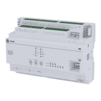
Figure 4. BACnet MS/TP link wiring
BI LINK IMC
+
VDC
AIAIAI AI AI
P P
TX
RX
LINK I M
SERVI
SERVICE TOOL
IM
BI LINK IMC
+
VDC
AIAIAI AI AI
P P
TX
RX
LINK I M
SERVI
SERVICE TOOL
IM
BI LINK IMC
+
VDC
AIAIAI AI AI
P P
TX
RX
LINK I M
SERVI
SERVICE TOOL
IM
+
+
Symbio 500
Tracer SC+
Zone SensorsTrane BACnet
Terminator
Zone sensor
communications
jack wiring.
Symbio 500
Symbio 500
Wiring Best Practices
To ensure proper network communication, follow the recommended wiring and best practices below
when installing communication wire:
• All wiring must comply with the National Electrical Code™ (NEC) and local codes.
• Ensure that 24 Vac power supplies are consistent in regards to grounding. Avoid sharing 24 Vac
between controllers.
• Avoid over tightening cable ties and other forms of cable wraps. This can damage the wires inside
the cable.
• Do not run communication cable alongside or in the same conduit as 24 Vac power. This includes
the conductors running from TRIAC-type inputs.
• In open plenums, avoid running wire near lighting ballasts, especially those using 277 Vac.
• Use same communication wire type, without terminators, for the zone sensor communication stubs
from the Symbio 500 controller IMC terminals to the zone sensor communication module.
• Zone Sensor communication wiring length limits of 300 ft. (100 m).
Setting Up the Controller on a BACnet Link
Observe the following when setting up the Symbio 500 controller on a BACnet link.
• Use 18 AWG shielded communication wire for BACnet MS/TP installations.
• Limit BACnet MS/TP wiring links to 4,000 ft. There is a maximum of 60 devices per link (without a
repeater).
• Three (3) BACnet links are available on the Tracer SC+.
• Connect the BACnet link to the Symbio 500 controller terminals labeled Link as shown on the right.
Incoming wires can be connected to the first two terminals, and the outgoing wires can be
connected to the second set of terminals, so there is only one wire per termination.
Wiring
 Loading...


