32
BAS-SVX090B-EN
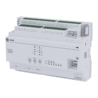
Figure 12. 0–20 mA analog inputs
VAC
24
XFRM
VAC
24
VAC
24
BI
1
BI
2
BI
3
BI
4
AO1
BI
5
AO2
UI
1
UI
2
AI
3
AI
2
AI
1
AI
4
IM
C
1
VAC
24
VAC
24
BI
1
BI
2
BI
3
LINK
IMC
+
24
VDC
BI
5
AO2
UI
1
UI
2
AI
3
AI
2
AI
1
AI
4
AI
5
P
1
P
2
TX
RX
LINK
IMC
IM
C
3-Wire
0-20 mA sensor
(current source)
2-Wire
0-20 mA sensor
(current controller)
Tape back shield wire, 2x
Shield Wire
Shield Wire
Common
0-20 mA Out
0-20 mA Out
24 Vdc
1000 ft
(300 m)
max.
1000 ft
(300 m)
max.
24 Vdc
To wire a 0–20 mA analog input:
1. Connect the shield to a common terminal at the terminal board and tape it back at the input device.
Note: Do not use the shield as the common connection. For 3-wire applications, use a 3-conductor
cable with shield and for 2-wire applications, use a 2-conductor cable with separate shield.
2. Connect the signal wire to an available universal input terminal.
3. Connect the supply wire to a 24 Vdc or 24 Vac terminal as required.
4. Use the Tracer TU service tool to configure the universal input for analog operation.
Variable Resistance Analog Inputs
Variable resistance analog inputs include 10K thermistors, resistive, and setpoint thumb wheels on zone
sensors. The illustration below shows a typical wiring for analog inputs, variable resistance.
Wiring
 Loading...


