38
BLACK
RED
GREEN - GROUND
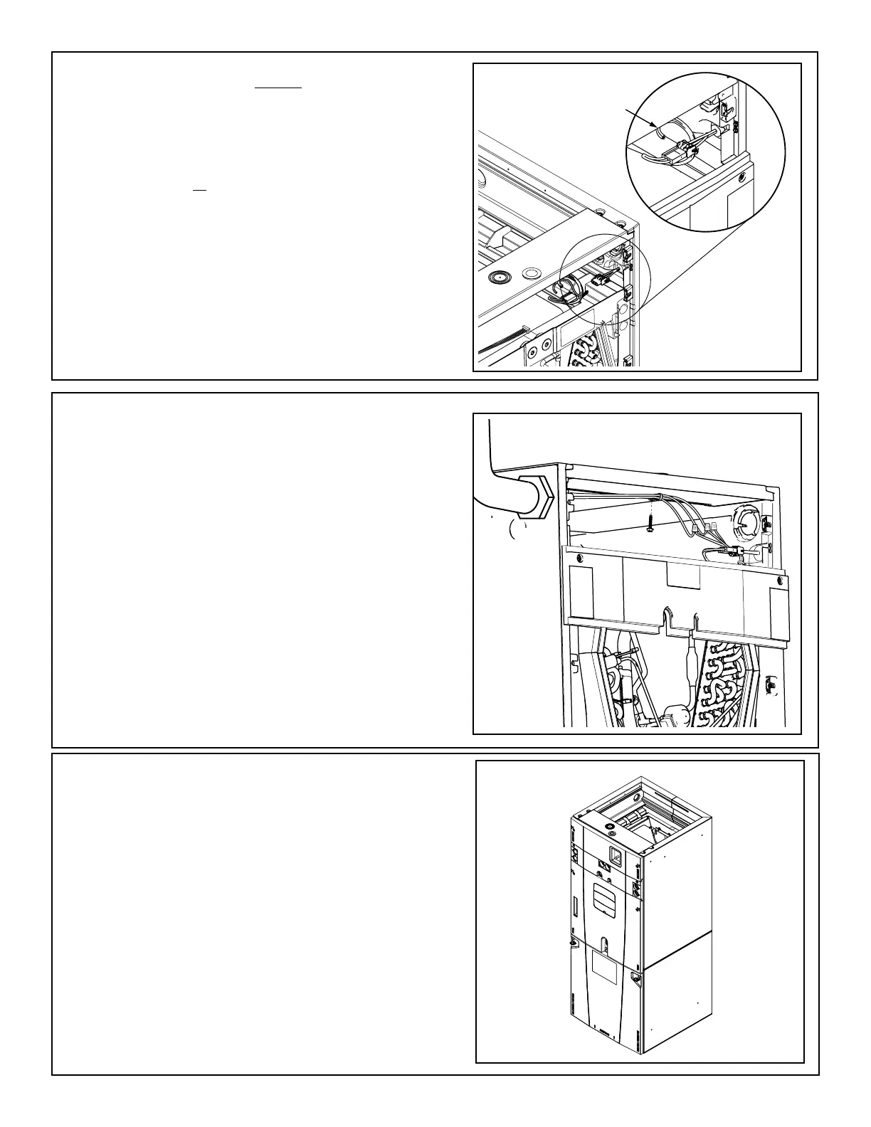
STEP 5 - If the L1, L2, and ground wires enter
the case from the left side, use a field supplied
1/2”-5/8” maximum length screw and wire tie to
hold the wires to the top center of the Heater
Compartment.
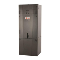
STEP 4 - If an electric heater IS NOT being
installed, remove the pigtail harness from the
documentation pack and connect it to the plug
on the inside of the Heater Compartment in the
cabinet.
If an electric heater IS being installed, see
the Installer’s Guide shipped with the electric
heater.
Connect L1, L2, and ground wiring to pigtail
harness in Heater Compartment using wire
nuts. The incoming ground wiring will mate up
with the green wire shown in the illustration.
STEP 6 - Reinstall all panels before starting the air
handler.
NOTE: After replacing all panels, loosen the Line
Set Panel screws approximately 1/4 - 1/2 turn. This
will improve the seal between the Heater Panel and
Line Set Panel.
 Loading...