ARTC-SVX013A-EN
21
Control Architecture
The control architecture is broken down in the following
categories:
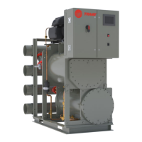
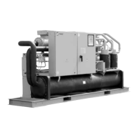
• Basic Controls – considers both standard water-cooled
and air-cooled chillers
– Standards
– Menus
– Data Displays
• Special Functions
– Hand/Off/Auto
– Chiller Setpoint Control
– Enhanced EXV Control
– Condenser/Fan/Cooling Tower Control/Bypass
Valve
– Tonnage and Power Calculations
– Metric/Imperial Display
– BMS Interconnectivity
– Compressor Staging Valve Control
• Optional Functionalities
– Free Cooling
– Pump and Plant Controls
– Data Logging
– Master/Slave
– Controller option
– Economizer
– Hot Gas Bypass Valve
– Low-Lift Application
• Security Configuration
• Alarm Handling
Basic Controls
This section describes the basic functions of the chiller
control system.
• Standards and common features
• Menus
• Data Displays
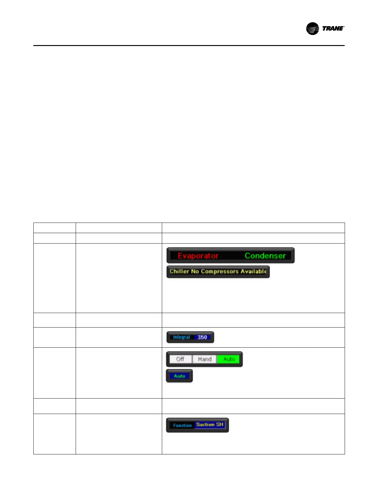
Display Common Features
Display Feature Description User Interface
Static Text Static text is light or dark Cyan
Dynamic Text Dynamic text is context sensitive under
the following guidelines.
• Evaporator – No Flow
• Condenser – Flow
• Green indicates OK, Active, Enable
or Normal.
• Red indicates Off, inactive, Disable
or Fault.
• Yellow indicates warning or potential
problem.
Dynamic Numeric
Data
Dynamic numeric data is White
User Numeric Data User Numeric data (settings and
Setpoints) White in a Blue box:
Device HOA
Control
Device HOA Control has 2 versions:
• Off, Hand and Auto is generally used
on pop-up setup windows.
• Auto is used on device control
pages. It is a multi-option click
control which indicates each user
click rotates to the next option –
Auto-Off-Manual then back to Auto.
User Button User buttons are generally blue with white
text with some exceptions.
User Option
Controls
User option controls are multi-colored text
values in a blue box.
• Colors indicate a different selection.
• Used for Device Algorithmic
selection and Function Option
selections
Operating Procedures