ARTC-SVX013A-EN
55
Free Cooling
The free cooling option comes with the T3C Companion
Controller. See the following figure.
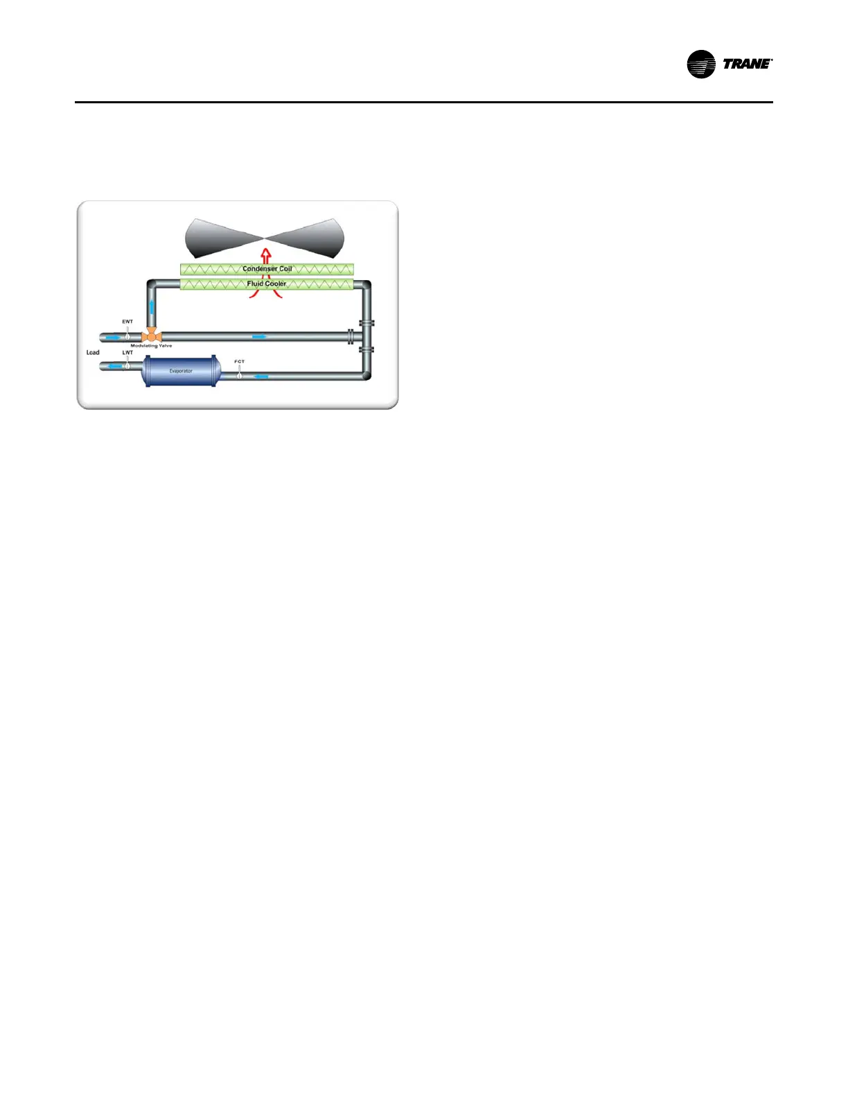
Figure 29. Free cooling block diagram
The free cooling option allows the user to leverage the
equipment to use lower ambient temperatures. The free
cooling chiller uses the following components.
• Free Cooler Coil – This coil is mounted next to the
condenser coil to allow airflow through the fluid cooler
first.
• Modulating Valve
– When the system is not using the free cooling
capabilities, the ambient temperature is too high to
gain any cooling from the environment, the
modulating valve is at 0 percent or closed and all
the chilled water flow goes from the load directly to
the evaporator. This mode is called full mechanical
cooling.
– When the temperature drops below a configurable
temperature threshold, the valve opens to 100
percent and all chilled water flow goes through the
fluid cooler before going to the evaporator. The two
components are now in series with respect to
chilled water flow. This mode is called pre-cool/free-
cool.
– Under extreme conditions, when the temperature is
cool enough for the fluid cooler to provide extreme
cooling, the valve modulates to reintroduce load
into the chilled water flow to maintain temperature
setpoint.
• Temperature Sensors –
– Entering Water Temperature (EWT) – EWT is the
return temperature from the load.
– Free Cool Temperature (FCT) –FCT is the
temperature after flow has passed through the fluid
cooler. In mechanical mode FCT = EWT.
– Leaving Water Temperature (LWT) –LWT is the
temperature supplied to the load. This equals the
setpoint of the chiller.
Mechanical Mode
The chiller, working in mechanical mode, derives all cooling
from the compressors. The modulating valve is closed and
no flow goes to the fluid cooler. The fans in the system are
dedicated to condenser cooling.
Pre-Cool Mode
In pre-cool mode, the modulating valve is open to 100
percent where water flows from the load through the fluid
cooler to the evaporator. In this case, the chiller is
extracting cooling capacity directly from the environment.
The chiller control monitors FCT to decide to run
compressors. If FCT is greater than chiller setpoint, the
chiller cannot derive enough cooling from the environment
and is required to engage mechanical cooling. The
combination of mechanical with free-cooling is called the
pre-cooling mode.
Often, in pre-cool mode, all refrigeration circuits are not
required for mechanical cooling. These circuits would be
used entirely for free cooling, where the fans would drive to
100 percent.
Free-Cool Mode
In free-cool mode, the compressors are enabled and ready
but are off due to LWT being satisfied. FCT has satisfied
the setpoint and LWT = FCT. This mode is characterized by
all refrigeration circuits providing free cooling and the fans
are modulating to maintain setpoint. Free cooling is
extreme when the ambient temperature is very low, the
fans are off, and the fluid cooler still provides more capacity
than required. At this point, the modulating valve provides
setpoint control.
Free Cooling Controls
The HMI provides the following windows into the control of
the free-cool system.
• Free-Cool Fan Control
• Free-Cool Valve Control
Free-Cool Fan Control
The following HMI page provides standard function control
for the free-cool control of the fans on the chiller.
Operating Procedures