56
ARTC-SVX013A-EN
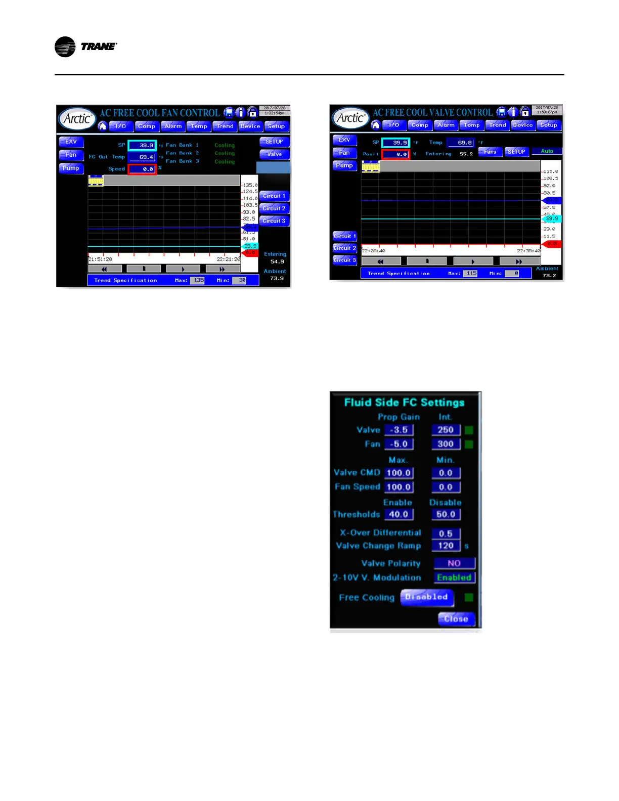
Figure 30. Free-cool fan control page
The following states shows differences from a standard
control page.
• Fan Bank State – the fans on the chiller are organized
into banks where a bank of fans acts in concert on a
single refrigeration circuit. The states of a fan bank are:
– Off – No activity. Auto control is ineffective.
– Ready – Not currently running but available for both
free and condenser cooling.
– Free-Cool – Providing free cooling and controlled
by chiller setpoint (displayed) on Fluid Cooler (FC)
outlet temperature.
– Start – Function on condenser cooling where the
circuit has just been engaged and the fans are
running at a preset constant speed.
– Cooling – follows after Start stage when the circuit
is in condenser cooling.
• Valve Control Access – Click the Valve button to
access the Free-Cool Valve control page.
• Multiple Circuit Access – use the Circuit x buttons to
access individual circuit fan control pages (mechanical
cooling) for auto/manual control of fan bank.
• Displays Ambient and entering water temperatures for
reference.
Free-Cool Valve Control Page
The following is the Free-Cool Valve Control Page.
Figure 31. Free-cool valve control page
This control page has some of the same features as the
Free-Cool Fan control page except this has free cooling
valve auto/manual/off control.
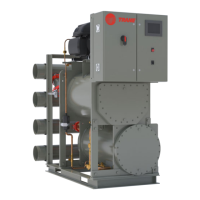
Free-Cool Setup Page
For both fan and valve control there is a common setup
page.
Figure 32. Free-cool configuration setup page
The Free-Cool Setup page has the following features:
• Parameters for independent control loops for valve and
fans
– P-Band
– Integral
– Maximum %
– Minimum %
Operating Procedures