EasyManuals Logo

Trane TCONT602AF22MA Installation Instructions

Trane TCONT602AF22MA
16 pages
To Next Page IconTo Next Page
To Previous Page IconTo Previous Page
Page #3 background imageLoading...
Page #3 background image
1
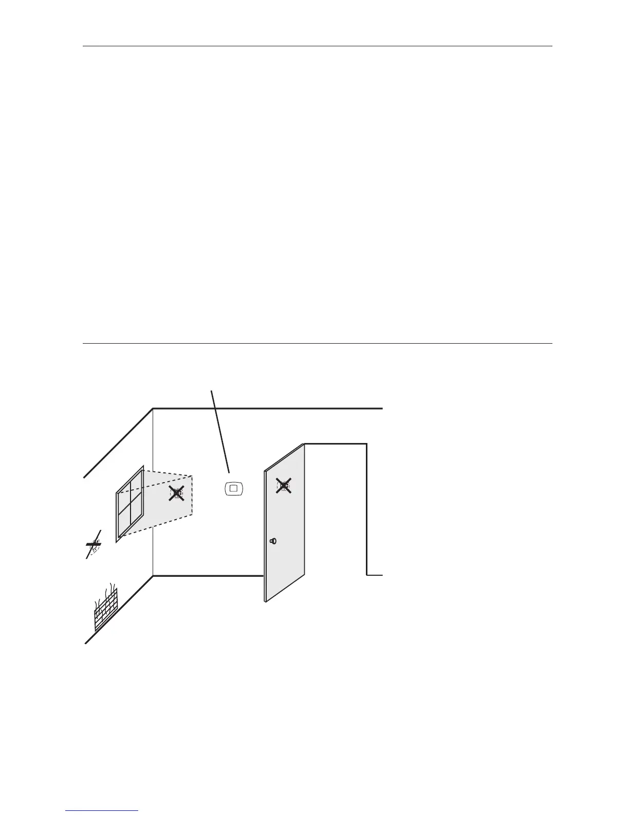
Install the Comfort Control about 5 feet (1.5m) above the floor in an
area with good air circulation at average temperature.
Do not install in locations where the Comfort Control can be affected by:
• Drafts or dead spots behind doors and in corners
• Hot or cold air from ducts
• Sunlight or radiant heat from appliances
• Concealed pipes or chimneys
• Unheated/uncooled areas such as an outside wall behind the Comfort Control
NO
NO
NO
Installation
Pre-installation checklist ................2
Wallplate installation ......................3
Wiring..............................................4
Wiring diagrams ..............................5
Power options ................................7
Comfort Control mounting ............7
Setup and testing
Installer setup..................................8
Installer system test ......................10
Explanation of features ................11
Appendices
Quick reference to controls..........12
Quick reference to display............12
Battery replacement......................12
In case of difficulty ......................13
Accessories/replacement parts ....14
Specifications ................................14
Table of contents
Installation tips

Other manuals for Trane TCONT602AF22MA

Questions and Answers:

Question and Answer IconNeed help?

Do you have a question about the Trane TCONT602AF22MA and is the answer not in the manual?

Trane TCONT602AF22MA Specifications

Temperature Ranges IconTemperature Ranges
heat temperature range40° to 90°F (4.5° to 32°C)
cool temperature range60° to 99°F (16° to 37°C)
operating ambient temperature32° to 120°F (0° to 48.9°C)
Humidity IconHumidity
operating relative humidity5% to 90% (non-condensing)
Electrical Ratings IconElectrical Ratings
W (O) heating voltage20-30 Vac
W (O) heating current0.02-1.0 A
W1 W2 heating voltage20-30 Vac
W1 W2 heating current0.02-0.5 A
Y cooling voltage20-30 Vac
Y cooling current0.02-1.0 A
Y2 cooling voltage20-30 Vac
Y2 cooling current0.02-1.0 A
G fan voltage20-30 Vac
G fan current0.02-0.5 A
X2 emergency heat voltage20-30 Vac
X2 emergency heat current0.02-1.0 A
F heat pump reset voltage20-30 Vac
F heat pump reset current0.02-0.5 A
Weight and Dimensions IconWeight and Dimensions
height3-9/16” (91 mm)
width5-13/16” (147 mm)
depth1-1/2” (38 mm)

Related product manuals