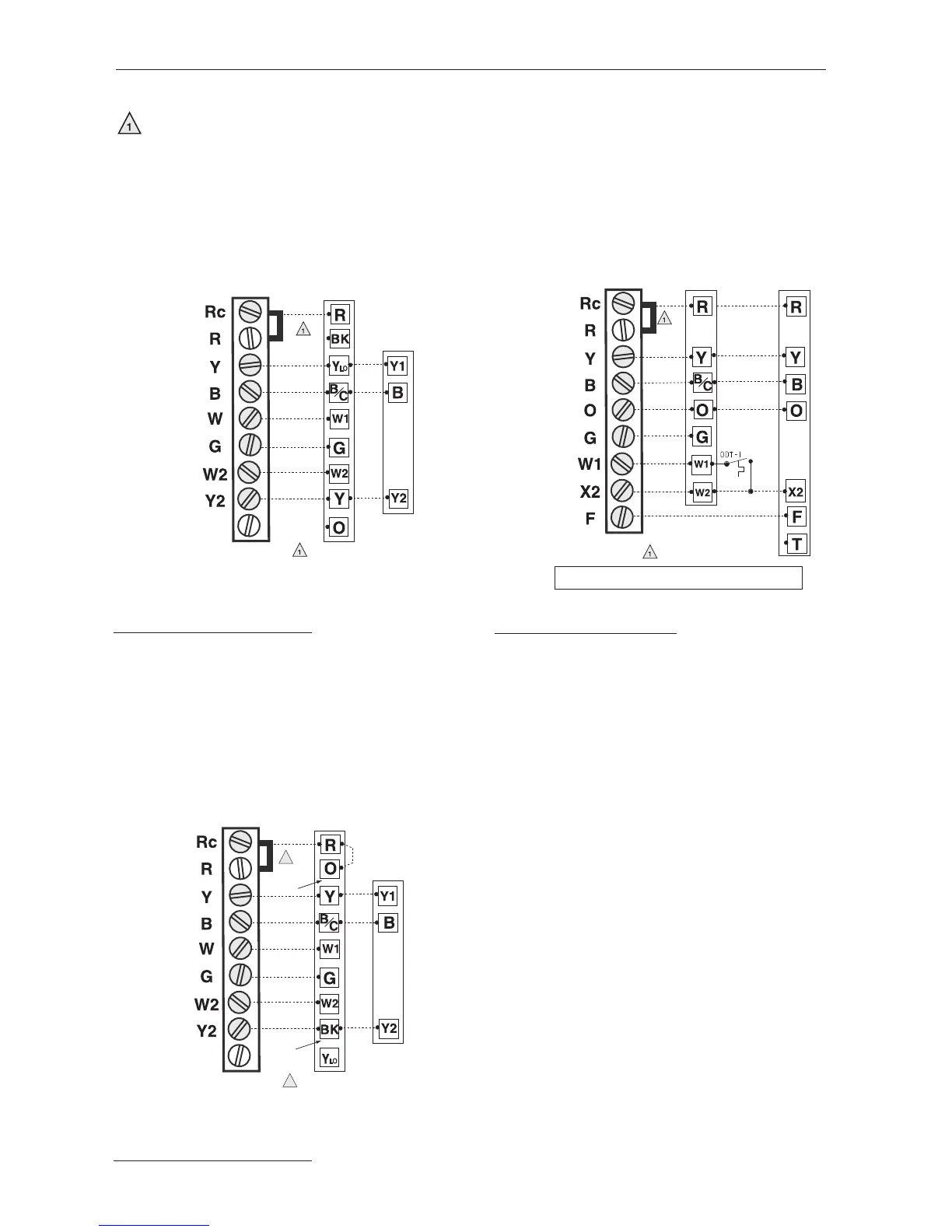
EasyManuals Logo

Trane TCONT602AF22MA Installation Instructions

Trane TCONT602AF22MA
16 pages
To Next Page IconTo Next Page
To Previous Page IconTo Previous Page
Page #8 background imageLoading...
Page #8 background image
6
Wiring diagrams
Typical 2H/2C system (1 transformer) Typical 2H/1C heat pump system
2H/2C 16 SEER cooling system
Factory-installed jumper. Remove for 2-transformer systems only.
• Provide Power Supply disconnect means and overload protection as required
In Installer Setup, set system type to
2Heat/1Cool Heat Pump.
F terminal is powered continuously when
Comfort Control is set to Em Heat.
Install field jumper between W1 and X2 if there
is no emergency heat relay.
In Installer Setup, set system type to
2Heat/2Cool Conventional.
In Installer Setup, set system type to
2Heat/2Cool Conventional.
24VAC HOT
24VAC
602 COMFORT CONTROL
TERMINAL BLOCK
TWO STAGE VARIABLE SPEED GAS FURNACE – TWO STAGE COOLING
TWO STAGE
AIR CONDITIONER
FAN
COOLING-1st
HEATING-1st
HEATING-2nd
TWO STAGE
VARIABLE SPEED
GAS FURNACE
FACTORY INSTALLED JUMPER.
COOLING-2nd
24VAC HOT
24VAC
602 COMFORT CONTROL
TERMINAL BLOCK
TWO STAGE 16 SEER COOLING – TWO STAGE GAS FURNACE
TWO STAGE
16 SEER
AIR CONDITIONER
FAN
COOLING-1st
HEATING -1st
HEATING -2nd
TWO STAGE
VARIABLE SPEED
GAS FURNACE
1
FACTORY INSTALLED JUMPER.
1
COOLING-2nd
Note A - The installer must jumper at the LVTB "R" to "O"
Note B - Cut/remove the factory installed "BK" jumper.
Note A
Note B
HEAT PUMP
– AIR HANDLER -ELECTRIC HEATER 2H/1C
HEAT PUMP
AIR HANDLER &
ELECTRIC HEAT
NOTE:
IF ODT-1 IS NO
T USED, THEN CONNECT A JUMPER WIRE FROM W1 TO W2.
24VAC HOT
24VAC
FAN
COMPRESSOR
SOV
HEATER
EM. HEAT
FAULT
FACTORY INSTALLED JUMPER.
602 COMFORT CONTROL
TERMINAL BLOCK

Other manuals for Trane TCONT602AF22MA

Questions and Answers:

Question and Answer IconNeed help?

Do you have a question about the Trane TCONT602AF22MA and is the answer not in the manual?

Trane TCONT602AF22MA Specifications

Temperature Ranges IconTemperature Ranges
heat temperature range40° to 90°F (4.5° to 32°C)
cool temperature range60° to 99°F (16° to 37°C)
operating ambient temperature32° to 120°F (0° to 48.9°C)
Humidity IconHumidity
operating relative humidity5% to 90% (non-condensing)
Electrical Ratings IconElectrical Ratings
W (O) heating voltage20-30 Vac
W (O) heating current0.02-1.0 A
W1 W2 heating voltage20-30 Vac
W1 W2 heating current0.02-0.5 A
Y cooling voltage20-30 Vac
Y cooling current0.02-1.0 A
Y2 cooling voltage20-30 Vac
Y2 cooling current0.02-1.0 A
G fan voltage20-30 Vac
G fan current0.02-0.5 A
X2 emergency heat voltage20-30 Vac
X2 emergency heat current0.02-1.0 A
F heat pump reset voltage20-30 Vac
F heat pump reset current0.02-0.5 A
Weight and Dimensions IconWeight and Dimensions
height3-9/16” (91 mm)
width5-13/16” (147 mm)
depth1-1/2” (38 mm)

Related product manuals