Installation Guide
20 18-HD72D1-6
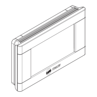
Diagram 25 - 1 Stage Heat Pump w/TEM4 Air Handler
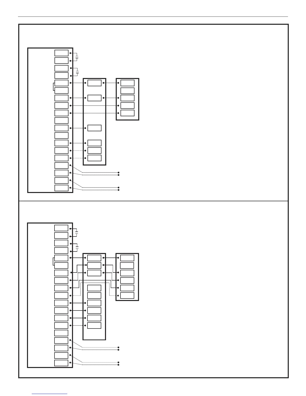
Diagram 26 - 1 or 2 Stage Heat Pump w/TEM6 Variable Speed Air Handler
X2
AUX 1
AUX 2
24VAC HOT
COMMON
SOV
COOLING
FA N
HEATING
ODT
RS
AUX1
AUX1
AUX2
AUX2
RC
RH
B/C
O
Y1
Y2
Y
G
BK
W1
W2
G
W1
W3
W2
W3
ODT
ODT
RS1
RS1
O
R
B
R
B
Optional
Outdoor
Sensor*
Optional
Remote
Sensor*
1
25- 1 STAGE HEAT PUMP W/TEM4 MODEL AIR HANDLER
824 COMFORT CONTROL
INDOOR UNIT OUTDOOR UNIT
NOTES:
1. Connection to X2 is not required for this
configuration
*Caution: Do not run Outdoor/Remote
sensor wires in the same bundle
with HVAC wires. Also, keep away
from high voltage wiring to avoid
interference.
X2
AUX 1
AUX 2
24VAC HOT
COMMON
SOV
COOLING
FA N
HEATING
ODT
RS
AUX1
AUX1
AUX2
AUX2
R
RH
B/C
O
Y1
Y2
Y2
G
BK
W1
W2
Y2
G
BK
W1
W3
W2
ODT
ODT
RS1
RS1
Y1
O
R
B
O
Y1
R
B
Optional
Outdoor
Sensor*
Optional
Remote
2
1
26- 1 OR 2 STAGE HEAT PUMP W/TEM6 MODEL VARIABLE SPEED AIR HANDLER
824 COMFORT CONTROL
INDOOR UNIT OUTDOOR UNIT
NOTES:
1. Remove the factory installed BK jumper at the
indoor unit
2. Connection to X2 is not required for this
configuration
3. R & Y2 connections at outdoor are only required for
two stage units
*Caution: Do not run Outdoor/Remote
sensor wires in the same bundle
with HVAC wires. Also, keep away
from high voltage wiring to avoid