824 Programmable Wi-Fi Comfort Control
18-HD72D1-6 7
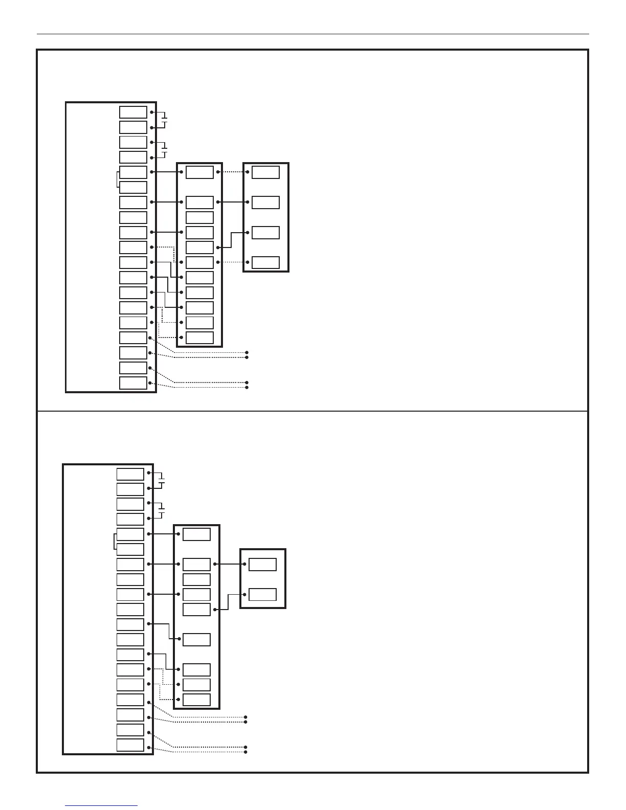
4.5 Heat/Cool Applications
Diagram 1 - 1 or 2 Stage Cooling w/TAM7 Model Variable Speed Air Handler
Diagram 2 - 1 Stage Cooling w/GAM5A or TAM4 Model Air Handler
AUX 1
AUX 2
24VAC HOT
COMMON
SOV
COOLING
FA N
HEATING
ODT
RS
AUX1
AUX1
AUX2
AUX2
RC
RH
B/C
O
Y1
Y2
G
BK
W1
W2
W3
ODT
ODT
RS1
RS1
O
R
B
YI
YO
W3
Y2
G
BK
W1
W2
R
B
Y/Y1
Y2
Optional
Outdoor
Sensor*
Optional
Remote
Sensor*
3
2
1
4
4
824 COMFORT CONTROL
1- 1 OR 2 STAGE COOLING W/TAM7 MODEL VARIABLE SPEED AIR HANDLER
INDOOR UNIT
OUTDOOR UNIT
NOTES:
1. Cut and remove the BK jumper at the indoor unit
AFC Board
2. YI and YO connections must be made as shown
for freeze protection and internally mounted
condensate overflow circuits to function properly
3. If a 3rd party overflow condensate switches are
installed, wire between Y1 of the 824 and YI of the
airflow control board
4. R and Y2 connections at outdoor unit are required
only for two stage units
*Caution: Do not run Outdoor/Remote
sensor wires in the same bundle
with HVAC wires. Also, keep away
from high voltage wiring to avoid
interference.
AUX 1
AUX 2
24VAC HOT
COMMON
SOV
COOLING
FA N
HEATING
ODT
RS
AUX1
AUX1
AUX2
AUX2
RC
RH
B/C
O
Y1
Y2
G
BK
W1
W2
W3
ODT
ODT
RS1
RS1
O
R
B
YI
YO
W3
G
W1
W2
B
Y
Optional
Outdoor
Sensor*
Optional
Remote
Sensor*
2
1
*Caution: Do not run Outdoor/Remote
sensor wires in the same bundle
with HVAC wires. Also, keep away
from high voltage wiring to avoid
interference.
2- 1 STAGE COOLING W/GAM5A OR TAM4 MODEL AIR HANDLER
824 COMFORT CONTROL
INDOOR UNIT
OUTDOOR UNIT
NOTES:
1. YI and YO connections must be made as shown for
freeze protection and internally mounted condensate
overflow circuits to function properly
2. If 3rd party overflow condensate switches are
installed, wire between Y1 of the 824 and YI of the
air handler