Installation Guide
22 18-HD72D1-6
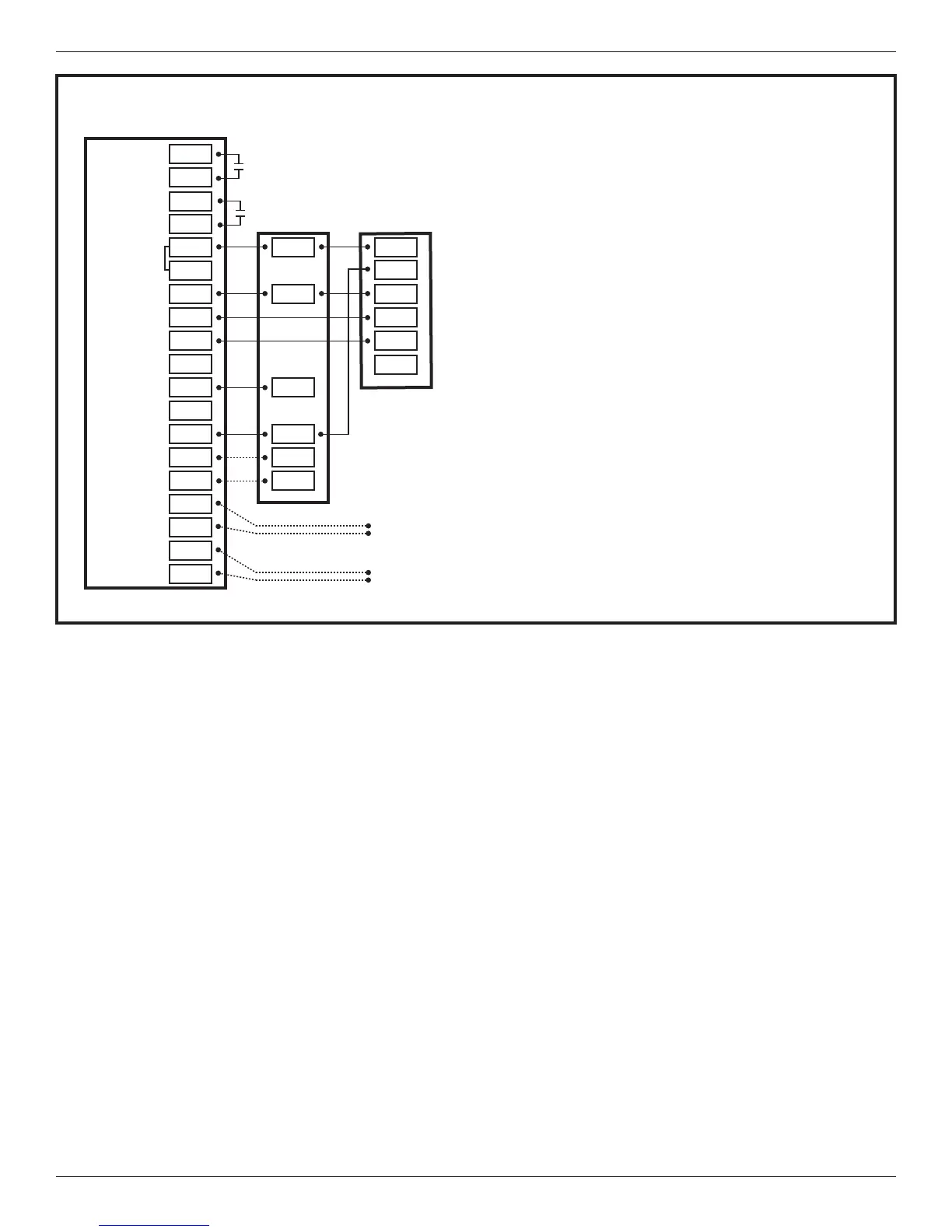
Diagram 29 - Ameristar 1 Stage Heat Pump
X2
AUX 1
AUX 2
24VAC HOT
COMMON
SOV
COOLING
FA N
HEATING
ODT
RS
AUX1
AUX1
AUX2
AUX2
RC
RH
B/C
O
Y1
Y2
Y
G
BK
W1
W2
G
W1
W3
W2
W3
ODT
ODT
RS1
RS1
B
R
C
R
D
C
Optional
Outdoor
Sensor*
Optional
Remote
Sensor*
4
NOTES:
1. D at the Outdoor Unit must be wired to W1 or W2 for
electric heat during defrost
2. B/C at the Control is 24v common and must be
connected to C at the Indoor and Outdoor Units
3. O at the Control must be connected to B at the
Outdoor Unit for SOV operation - SOV must also be
configured to be energized in heating mode in the
824 Installer Settings>Standard
4. Connection to X2 is not required for this
configuration
29 - AMERISTAR 1 STAGE HEAT PUMP
824 COMFORT CONTROL
INDOOR UNIT OUTDOOR UNIT
1
2
3
3
2
*Caution: Do not run Outdoor/Remote
sensor wires in the same bundle
with HVAC wires. Also, keep away
from high voltage wiring to avoid
interference.