BAS-SVX36C-EN 13
Installation
2. Align the pins on the circuit board with the holes on the bottom of the terminal blocks and gently
push the wired terminal blocks into place on the circuit board. See Figure 5.
Figure 5. Attaching the wired terminal blocks to the pins on the circuit board
C G Y W Rc R
W2(W1)
Y2
S1
S2
R
Rc
Y
G
C
W(O/B)
A
W2 Y2 A S1 S2
Rc R Y C O/B G
AuxE
Y2 L
R
Rc
Y
G
W2(AuxE)
Y2
L
C
W (O/B)
Rc R Y C W G
R
Rc
Y
G
C
W
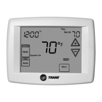
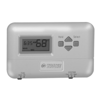
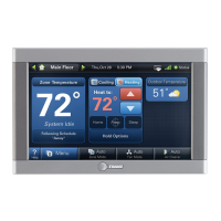
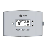
Programmable thermostat 3-Heat/2-Cool thermostat 1-Heat/1-Cool thermostat
s
3. Push the excess wire through the hole in the wall cavity or into the junction box.
Important: Do
not coil excess wire between the thermostat and the back plate.
4. Use nonflammable insulation to prevent air movement between the wall cavity and the
thermostat.
Terminal Identification
The table below defines the terminals for each of the thermostat types.
Terminal
Label Terminal Description
Where present:
1H/1C Thermostat
(p/n X13511535-01)
3H/2C Thermostat
(p/n X13511536-01)
Programmable
Thermostat
(p/n X13511537-01)
C Common
G Fan Relay
Y Stage 1 compressor control
W (O/B) Heat relay (Changeover valve)
(1)
(1) Text (in parentheses) applies to heat pump systems.
Rc 24Vac cooling These terminals are shipped with a jumper connected
between them. Remove the jumper if the 24Vac power
supplies are separate.
R 24Vac heating
W2 (W1)
or
W2 (Aux/E)
Second stage heat (Auxiliary heat or emergency heat relay.)
(1)
Y2 Stage 2 compressor control
A Economizer
S1 External sensor
S2 External sensor
(L) (Emergency heat indicator)
(1)

 Loading...