14 BAS-SVX36C-EN
Installation
Wiring Diagrams
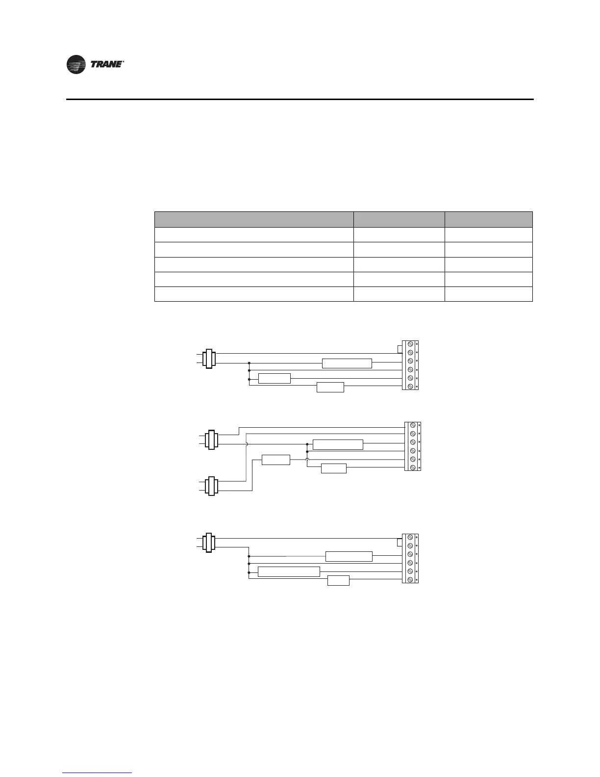
The following diagrams show all of the common wiring scenarios you are likely to encounter.
1-Heat/1-Cool Thermostat
Use Table 3 and the diagrams that follow to correctly wire the thermostat for your system type.
Figure 6. 1H/1C Thermostat, 1H/1C Conventional (option 0)
Single Transformer:
(jumper
installed)
Rc
R
Y
C
W
G
Fan
L2
L1 (hot)
24 Vac
Heat
Compressor
Rc
R
Y
C
W
G
Fan
L2
L1 (hot)
24 Vac
Heat
Compressor
L2
L1 (hot)
24 Vac
Cooling Transformer
Heating Transformer
Two Transformers:
(jumper
removed)
Figure 7. 1H/1C Thermostat, 1H/1C Heat Pump Without Auxiliary Heat (Option 1)
(jumper
installed)
Rc
R
Y
C
O/B
G
Fan
L2
L1 (hot)
24 Vac
Changeover Valve
Compressor
Table 3. SystemType Options for 1H/1C Non-ProgrammableThermostats
System Type
Value for Option 01 See Diagram
1-heat/1-cool, conventional 0 Figure 6
1-heat/1-cool, heat pump without auxiliary heat 1 Figure 7
1-heat only, conventional without fan 2 Figure 8
1-heat only, conventional with fan 3 Figure 9
1-cool, conventional 4 Figure 10

 Loading...