Operating Procedures
ARTC-SVX002A-EN 29
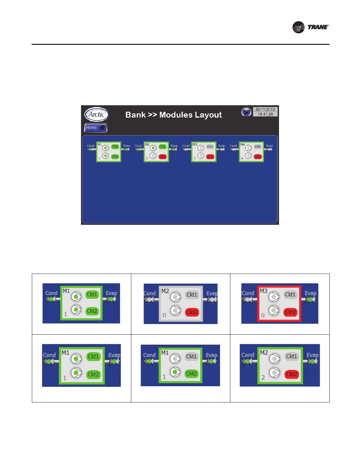
Modules Layout Screen
The chiller can be composed of up to a maximum of ten
modules. Pressing the LAYOUT button displays the screen
showing the status of compressors and valves in each
module. See below figure.
Each module diagram is a set of symbols and colors that
show the real-time status of the compressors, the
refrigeration circuit, the isolation valves and the module
overall. See figure below.
Module Layout Screen Status Conditions
Each module picture is a set of images that show real-time
color-coded state of compressor, refrigeration circuit,
isolation valves and module.
Figure 15. Modules layout screen showing four compressors on four modules
Table 3. Module status conditions
Module is available
Module is unavailable
Module turned off by alarm and unavailable
Refrigeration circuit in normal state;
Compressor ON
Refrigeration circuit is non-operational;
Compressor OFF
Refrigeration circuit in alarm state; compressor
OFF
 Loading...