36 CNT-SVX08F-EN
PID Control
20. Record the measured value when it stabilizes. The temperature stabilizes at 70°F (21°C).
21. Manually control the analog output to 50% or 100%. Control the output to 100% (completely
opening the heating valve).
22. Record the measured value when it stabilizes. The temperature stabilizes at 120°F (49°C)
23. Subtract the measured value determined in step 2 fro
m the measured value determined in step
4. This is the change in the measured value.
120 - 70 = 50°F (49 - 21 = 28°C).
24. Calculate two-thirds (66%) of the change in measured value determined in step 4. Add this value
to
the in
itial temperature to determine at what point two-thirds of the total change occurs.
In the example, 0.66 × 50°F = 33°F, so two thirds of the tota
l change
occurs at 70°F + 33°F = 103°F
(0.66 × 28°C = 18°C; 21 + 18 = 39°C).
25. Again, set the analog output to 0% and allow the measured value to stabilize. The measured
value stabilize
s at 70°F (21°C).
26. Control the output to the value used in step 3 and record the time
it takes to reach the two-thirds
point determined in step 6. This is the system time constant. The time it takes to reach 103°F
(39°C) is 2.5 minutes (150 seconds).
27. Divide the system time constant by 10 to determine
the starting samp
ling frequency.
150 seconds ÷ 10 = 15 seconds.
Note: Th
e system time constant is the time it takes
to reach 63.21% of the difference between the
start point and the end point. Determining two-thirds (66%) is accurate enough for our
purposes.
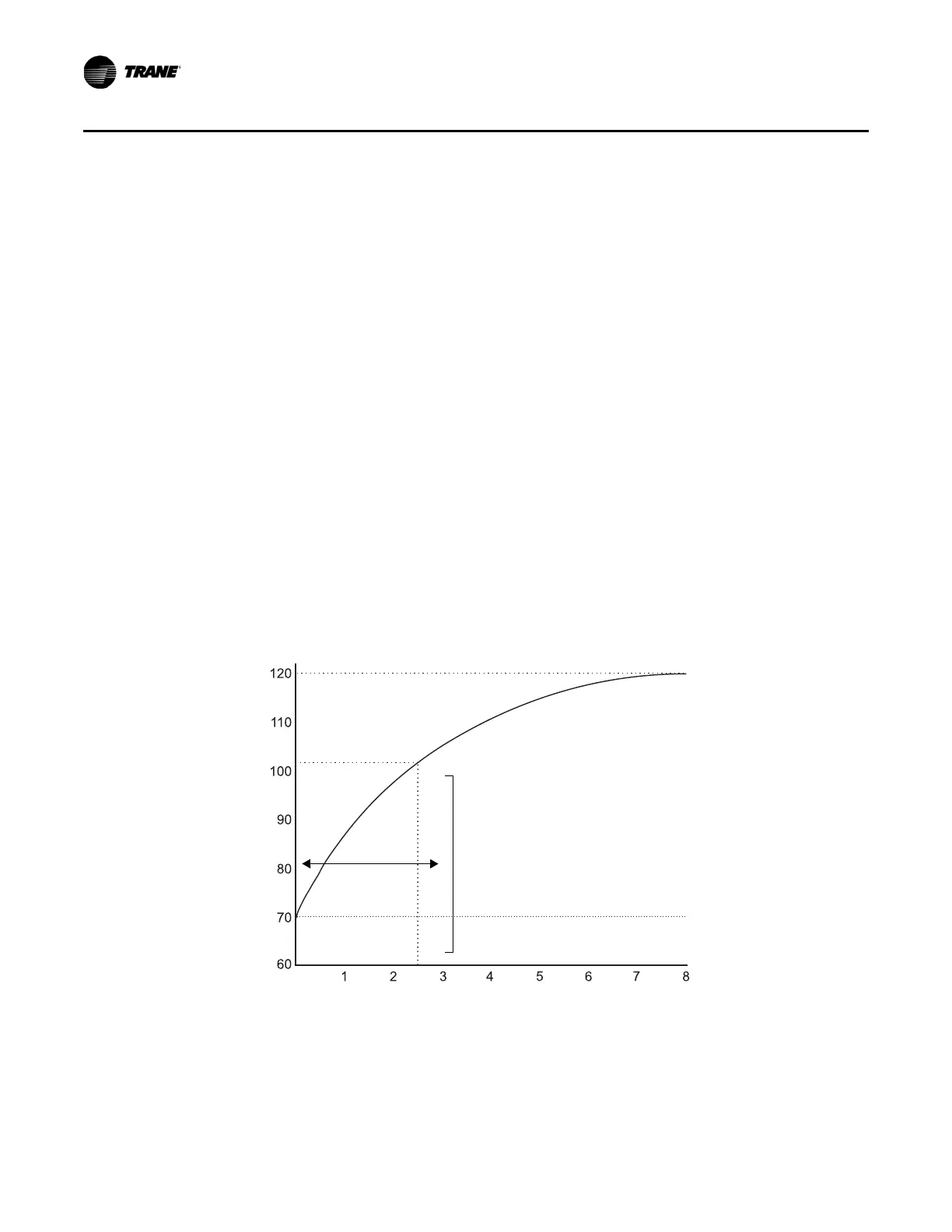
Figure 18 illustrates the procedure described above.
Figure 18. Determining the system time constant
System time
constant
Time (minutes)
Space temperature (°F)
Initial value (valve closed)
Final value (valve open)
2/3 of total change
Example
This scenario describes finding the sampling frequency for a PID loop controlling a heating
application.
28. Fully close the output.
29. The stabilized temperature reads 60°F (16°C).

 Loading...


