CNT-SVX08F-EN 49
Troubleshooting
The analog output generates a 0–10 Vdc control signal used to control valve, damper, pump speed,
fan speed, and so on. The PID loop in the MP501 calculates a value between 0 and 100%. The
controller then translates that percentage into the output voltage.
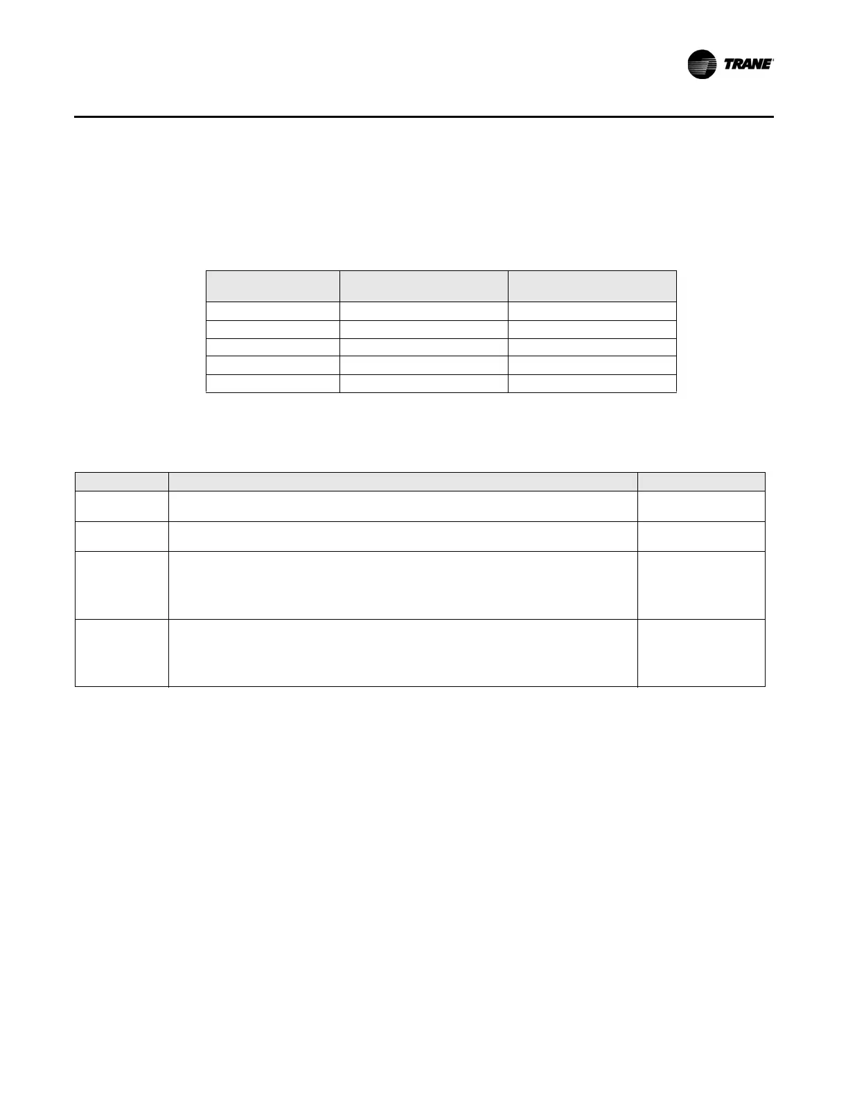
Table 20 lists the scaling for
typical analog output applications. This information will help to anticipate the voltage that is read,
given the PID output.
Table 20. Percent to voltage scaling for analog output
PID Output
Voltage Output
(0–10 Vdc Output)
Voltage Output
(2–10 Vdc Output)
0% 0.0 Vdc 2.0 Vdc
25% 2.5 Vdc 4.0 Vdc
50% 5.0 Vdc 6.0 Vdc
75% 7.5 Vdc 8.0 Vdc
100% 10.0 Vdc 10.0 Vdc
The troubleshooting steps in Table 21 assume the end device connected to the analog output is
always closed when the user believe it should be somewhat open and vice versa when closed.
Table 21. Analog output (0–10
Vdc) troubleshooting of external wiring
Step Number Action Probable Cause
Step 1
Perform the initial troubleshoot
ing steps described in Table 17, p. 47 and verify general board
operation is okay.
General board
problem.
Step 2
Inspect the wiring. Is there a good connection between the wire and the terminal blocks? Look
for sh
orts or opens. Pay particular attention to wire splices.
Wiring problem.
Step 3
Take your meter (set to measure dc voltage) and measure the voltage acro
ss the AO terminals
on the MP501.
If you see a value greater than 0 V, the problem lies beyond the MP501. Is the w
iring to the
equipment good? Is there a hardware override controlling the equipment?
If you see approximately 0 V, proceed to the next step.
Wiring problem.
Step 4
Remove the wires from the AO terminals and measure the voltage ag
ain.
If you see a value greater than 0 V, there is a wiring or equipment problem e
xternal to the
MP501.
If you still see approximately 0 V, the MP501 is commanding the output to be closed and you
need to i
nvestigate the MP501 further.
Wiring problem.
If the analog output is still not opening the end device, then follow the additional troubleshooting
steps in Table 22, p. 50. These steps will assist the configuration and operation of the analog
output.

 Loading...


