BAS-SVX48H-EN
9
Device Connections
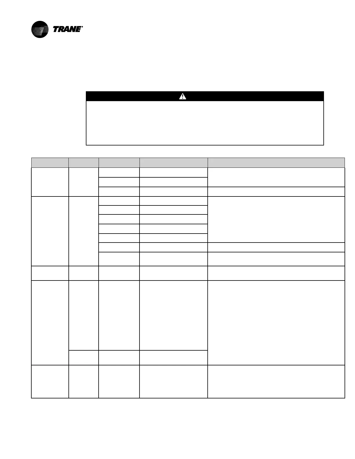
The following table provides details of the hardware termination configuration options. The
hardware terminations are pre-configured for proper equipment operation for blower coil/fan coil
applications.
WWAARRNNIINNGG
LLiivvee EElleeccttrriiccaall CCoommppoonneennttss!!
FFaaiilluurree ttoo ffoollllooww aallll eelleeccttrriiccaall ssaaffeettyy pprreeccaauuttiioonnss wwhheenn eexxppoosseedd ttoo lliivvee eelleeccttrriiccaall
ccoommppoonneennttss ccoouulldd rreessuulltt iinn ddeeaatthh oorr sseerriioouuss iinnjjuurryy..
WWhheenn iitt iiss nneecceessssaarryy ttoo wwoorrkk wwiitthh lliivvee eelleeccttrriiccaall ccoommppoonneennttss,, hhaavvee aa qquuaalliiffiieedd lliicceennsseedd
eelleeccttrriicciiaann oorr ootthheerr iinnddiivviidduuaall wwhhoo hhaass bbeeeenn pprrooppeerrllyy ttrraaiinneedd iinn hhaannddlliinngg lliivvee eelleeccttrriiccaall
ccoommppoonneennttss ppeerrffoorrmm tthheessee ttaasskkss..
Table 2. Connections
Connection
Quantity Types Range
Notes
Analog input
(AI1 to AI5)
5
Temperature
10 kΩ thermistor
AI1 to AI4 can be configured for timed override capability.
Setpoint
189 Ω to 889 Ω
Resistive 100 Ω to 100 kΩ
Typically used for fan speed switch.
Universal input
(UI1 and UI2)
2
Linear 0–20 mA
These inputs may be configured to be thermistor or resistive
inputs, 0–10 Vdc inputs, or 0–20 mA inputs.
Linear 0–10 Vdc
Temperature
10 kΩ thermistor
Setpoint
189 Ω to 889 Ω
Resistive 100 Ω to 100 kΩ
Binary Open collector/dry contact Low impedance relay contacts recommended.
Pulse
Solid state open collector Minimum dwell time is 25 milliseconds On and 25 milliseconds
Off.
Binary input
(BI1 to BI3)
(a)
3
24 Vac detect The UC400 controller provides the 24 Vac required to drive the
binary inputs when using the recommended connections.
Binary output
(BO1 to BO3)
(a)
3
UC400:Relay
• 2.88 A @24 Vac C pilot
duty
• Gen Purpose
– 10 A max up 277 Vac
– 10 A max up to 30 Vdc
• Motor Duty
– 1/3 hp @ 125 VAC
(7.5 A max)
– 1/2 hp @ 277 VAC
(7.5 A max)
Power needs to be wired to the binary output. All outputs are
isolated from each other and from ground or power.
Note: Ranges given are per contact.
Other
Ranges
UC400–B:TRIAC 24 Vac Powered
Binary output
(BO4 to BO9)
(a)
6 TRIAC
• UC400: 0.5 A max @24-
277 Vac, resistive and pilot
duty
• UC400–B: 24 Vac
Powered
Use for modulating TRIAC. User determines whether closing high
side (providing voltage to the grounded load) or low side
(providing ground to the power load).
Note: Ranges given are per contact and power comes from
TRIAC SUPPLY circuit.
 Loading...


