Coil Piping and Connections
58 UNT-SVX07J-EN
Valve and Actuator Operation
• Two position actuators are different for normally open
(N.O) and normally closed (N.C) and are capacitor
discharge return.
• Valve operation is the same.
• All actuators are clockwise to close and
counterclockwise to open with wire harness facing you
and looking at the top of the actuator.
Valve Stroke Time
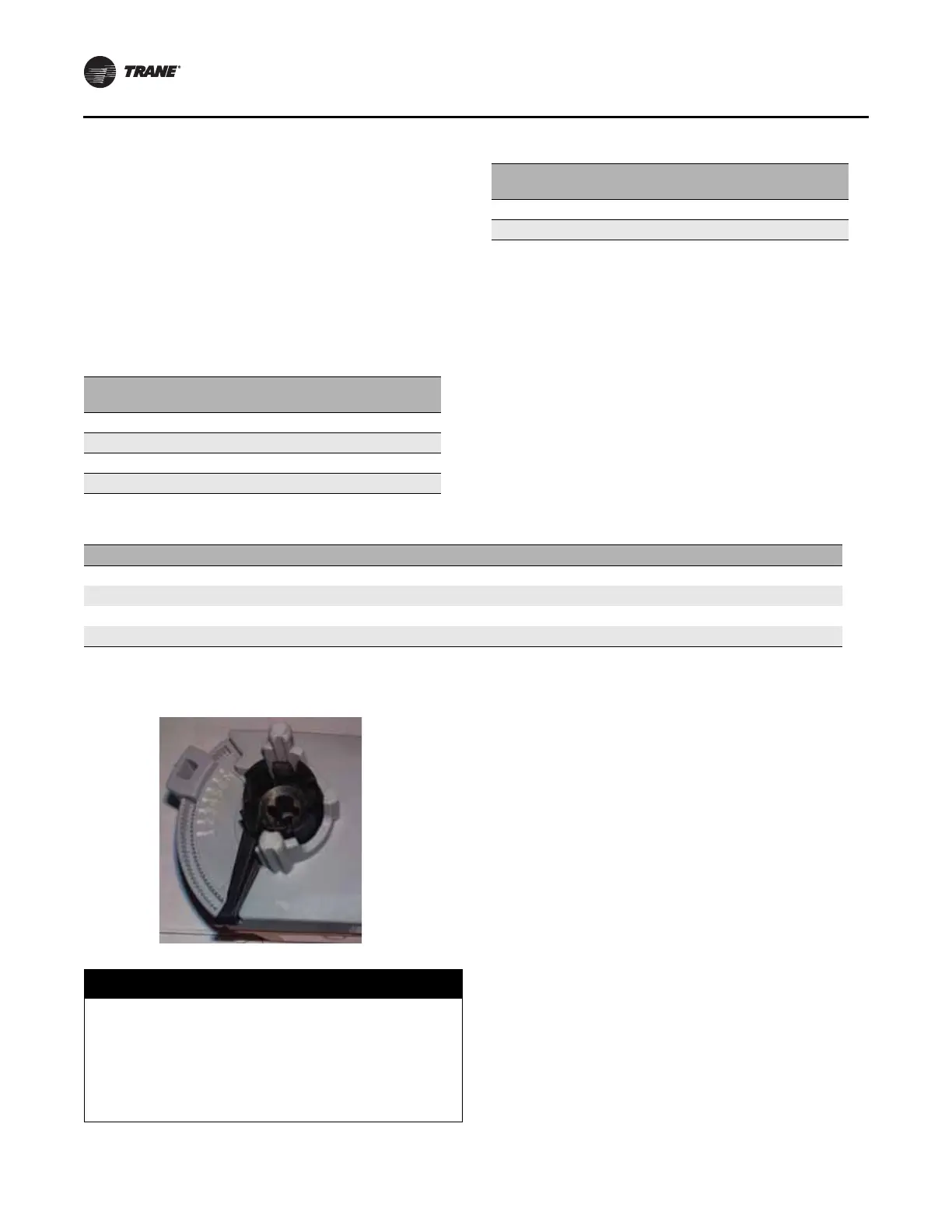
Field-Set Flow Capacity Adjustment
• If a different Cv is required, align the clip to the notch
scale found on the underside of the actuator to the
corresponding Cv in the table below.
• For 3-point floating, control signals adjust the
controller stroke time parameter to match the stroke
time of the final clip position.
• For all 3-way valves, the stroke time is 75 seconds and
there is no end stop on the actuator.
• The Cv can not be changed for 3-way valves.
Table 22. Valve stroke time
Valve Selection
End Stop
Position
Stroke Time
(Seconds)
1/2 in. 2-way 1.4 Cv No end stop 75
1/2 in. 2-way 2.4 Cv 5 55
3/4 in. 2-way 3.4 Cv 6 62
1/2 in. 3-way 1.0 Cv No end stop 75
1/2 in. 3-way 2.7 Cv No end stop 75
3/4 in. 3-way 4.6 Cv No end stop 75
Table 22. Valve stroke time (continued)
Valve Selection
End Stop
Position
Stroke Time
(Seconds)
Table 23. Actuator clip setting
2-way Valve Body 1 2 3- 3+ 4 4+ 5 5+ 6 N No End Stop
1/2 in. Z2050QS-F Cv 0.1 0.2 0.4 0.6 0.8 1.2 1.4(a)
1/2 in. Z2050QS-J Cv 0.5 0.7 1.2 1.7 2.4
(a)
3.4(a) 4.8 5.9
3/4 in. Z2075QS-K Cv 0.5 1 1.5 2.3 3.3 4.6 6.6 9.8
Stroke time (seconds) 30 37 41 43 49 51 55 58 62 68 75
(a) This Cv shows the standard Cv offering for 2-way valves.
Figure 36. Cv adjustments
Notice
Coil Damage!
Failure to do so could cause physical coil damage from
water hammer, unequal thermal stresses, freeze-up
and/or corrosion. In all steam coil installations, the
condensate return connections must be at the low
point of the coil to ensure condensate flows freely from
the coil at all times.