60 VAV-SVX01C-EN
Troubleshooting
Diagnostic Table
Use the Diagnostic Table (Table 13, p. 60) for failure parameters and Comm. 4 UCM actions to help
understand issue.
UCM Failure Procedures
In the event that the UCM is not operating, properly inspect the following:
• Incorrect supply voltage/No voltage
• The green LED indicates power and should be "steady" ON.
• Measure the power input to TB1-1 (power) and TB1-2 (ground) of the UCM board. The supply
voltage should be between 20 and 28 VAC (24 VAC cataloged). However, voltages at either
extreme may result in system instability.
• If no voltage, check up stream of controller to see were voltage has been interrupted. See
complete wiring diagrams, Figure 44 to Figure 51.
Important: For final step check program by downloading good program using Rover, see page
48.
UCM Communication Loss Procedures
In the event that the UCM is not communicating properly inspect the following:
1. Incorrect supply voltage/No voltage
• The green LED indicates power and should be "steady" ON.
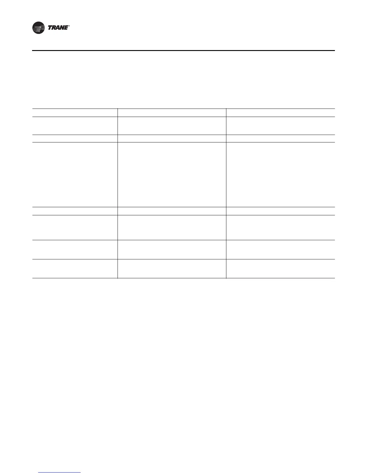
Table 13. Failure parameters and Comm. 4 UCM actions
Sensed Parameter Failure Criteria Action Taken
Zone Temperature
Open OR Short (> 25 seconds) AND no active
wireless sensors.
If failed open, control valve as if very cold
temperature. If failed shorted, control as if very hot
temperature.
Thumbwheel Setpoint Open OR short AND no active wireless sensors. Setpoints from EEPROM used.
Air Flow
For UCM 3.3 and prior, Flow < 10% when flow
control point > 10% OR flow > 110% or 150% for
series C.
For UCM 4, Flow < 5% when flow control point >
10% OR flow > 115% or 155% for series C.
UCM 4 will also indicate open/short for the air flow
sensor.
If unsuccessful at recovering flow signal, operate in
pressure dependent mode until flow signal
regained.
For UCM 4, if flow input is open or shorted the flow
failure flag will be set and pressure dependent mode
will be used.
UCM 3.3 is the only version that sets the failure flag
if the valve is flowing too much air (>110% or 150%
for series C)
Auxiliary Temperature Open or short Tracer supplied data used for auto changeover logic.
CO
(a)
Short or C0
2
value < 200 ppm
For UCM 4 with the aux input configured for C0
2
mode: if the C0
2
input is shorted or reading below
200 ppm, the Failed C0
2
sensor failure flag will be
set.
Supply Air Temperature
(b)
(VariTrac
Bypass Damper mode)
Open or short
For UCM 4 in bypass damper mode: if the SAT input
is shorted or open, the Failed SAT sensor failure flag
will be set.
Supply Air Pressure
(a)
(VariTrac Bypass
Damper mode)
Open or short
For UCM 4 in bypass damper mode: if the SAP input
is shorted or open, the Failed SAP sensor failure flag
will be set.
(a) UCM 4.0 and above will not detect an open. Instead, it will report 258 ppm.
(b) New to UCM 4.2