64 VAV-SVX01C-EN
Troubleshooting
Wireless Zone Sensor Failure Procedures
In the event that the UCM reports an incorrect zone Temperature/sepoint, properly inspect the
following:
Note: No special tools or software are necessary to service and test the wireless zone sensor
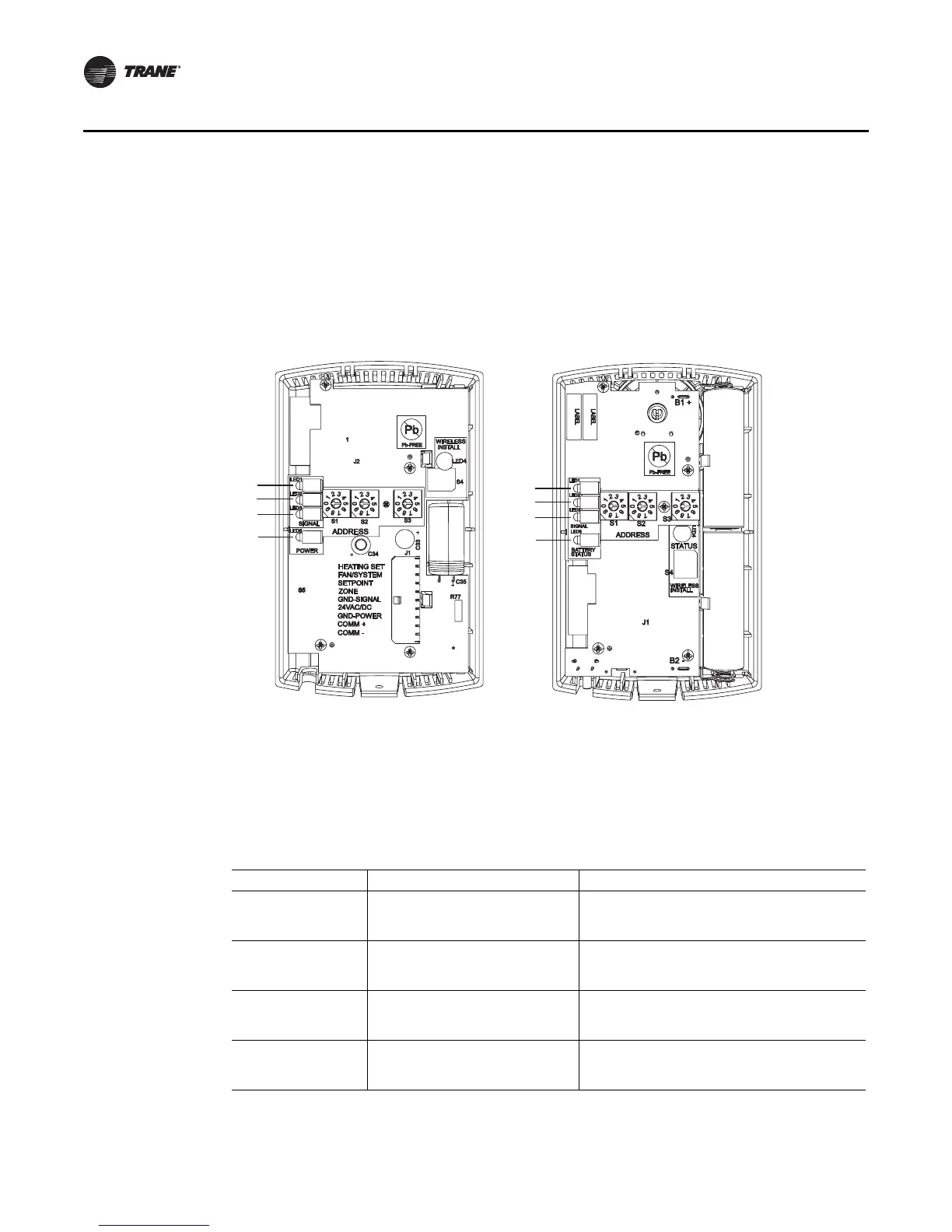
system. The system can be testing by using the following: 1) LEDs 1, 2, 3, and 5 on the sensor
and on the receiver; 2) The Test button (S5) on the sensor; 3) The address test mode on the
receiver; and 4) A common volt-ohm meter.
Diagnostics
Note: Reading diagnostics can show if the sensor has an issue or it has not been setup properly.
Use this information as a starting point
• LED1, LED2, and LED3 will respond to diagnostics by exhibiting specific blinking patterns. They
will occur on the sensor as a result of pressing the Test button (S5) (Table 18, p. 65). They will
occur on the receiver independently of any user action (Table 18, p. 65).
Figure 36. Wireless sensor set components with base plates removed
Table 15. Diagnostics: LED1, LED2, LED3 on the sensor
User Action LED Display
(a)
(a) Blink pattern is On for ¼ s, Off for ¼ s, with 2 s Off between repetitions.
Indicates…
Press Test
Button (SS)
LED1:Off
LED2:Off
LED3: 1-blink pattern repeated 3 times
Disassociated:
* Sensor is not associated with a receiver
Press Test
Button (SS)
LED1:Off
LED2:Off
LED3: 2-blink pattern repeated 3 times
Address set to 000:
* Address not set to between 001-999
Press Test
Button (SS)
LED1:Off
LED2:Off
LED3: 3-blink pattern repeated 3 times
Not Configured:
* Sensor configuration properties not properly set
(defective sensor)
Press Test
Button (SS)
LED1:Off
LED2:Off
LED3: 4-blink pattern repeated 3 times
Input Voltage Too High:
* No RF transmission is permitted with an input
battery voltage greater than 3/9 V
LED 1
LED 2
LED 3
LED 5
LED 1
LED 2
LED 3
LED 5