VAV-SVX01C-EN 75
Troubleshooting
• Fan relay should energize. If it does not check wiring. If wiring is OK replace fan relay
Note: UCM Outputs are switched to ground. Do not jumper 24 VAC to J9, J10, or J11 because
damage will occur.
8. After all checks have been completed, check motor fan winding integrity and bearing failure.
PSC Variable Speed Motor Check Out
If PSC Variable speed motor control not changing speed of the motor inspect the following:
• Wires connected improperly
• Check wiring to make sure speed control is wired correctly. See Figure 48, p. 83 and
Figure 49, p. 84 for wiring schematic.
• Check voltage selection switch on side of variable speed motor control.
• Should be set for motor voltage.
• To check speed control
• Turn voltage selection switch fully CCW
• Turn Motor speed control potentiometer fully CCW
• Motor should remain off
• Turn voltage selection switch fully CW
• Motor speed control potentiometer still fully CCW
• Measure motor voltage. Should be no more than 8VAC lower than line voltage
• With voltage selection switch still fully CW
• Turn Motor speed control potentiometer slowly fully CW (HI)
• Should go to full speed smoothly
If it fails any of these tests replace PSC motor speed controller.
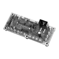
Testing ECM-DCU and ECM-VCU Fan Control
If ECM is not controlling Fan Motor properly inspect the following:
Note: The ECM controller has 4 wire pin connector that has an enable binary output and a Variable
speed analog output.
1. Incorrect supply voltage/No voltage
• Measure the power input to 24 VAC terminal and Common/ground terminal of the ECM
board. The supply voltage should be between 19.2 and 28.2 VAC (24 VAC cataloged).
However, voltages at either extreme may result in system instability.
• If low or no voltage, check up stream of controller to see how voltage has been interrupted.
See complete wiring diagrams (Figure 50, p. 85 and Figure 51, p. 86).
2. Testing Binary Output
• Measure voltage from White to Green wire on connector
• Should be between 9 to 30VDC. If not replace ECM
3. Testing Analog variable speed output
• On ECM-DCU change board selector switches to 0 on each one of the switches to give a 100%
output signal. On ECM-VCU adjust potentiometer until LED's read a 100% output.
• Measure voltage from green to red wires on 4 pin connector and document. See Figure 50,
p. 85 and Figure 51, p. 86 for correct unit wiring diagram.
• Should measure above 9VDC
• Change ECM-DCU board selector switches to 9 on tens digit an 9 on units digit to give a 99%
output signal. On ECM-VCU adjust potentiometer until LED's read a 99% output