BAS-SVX40A-EN 13
Mounting and Wiring the WCI
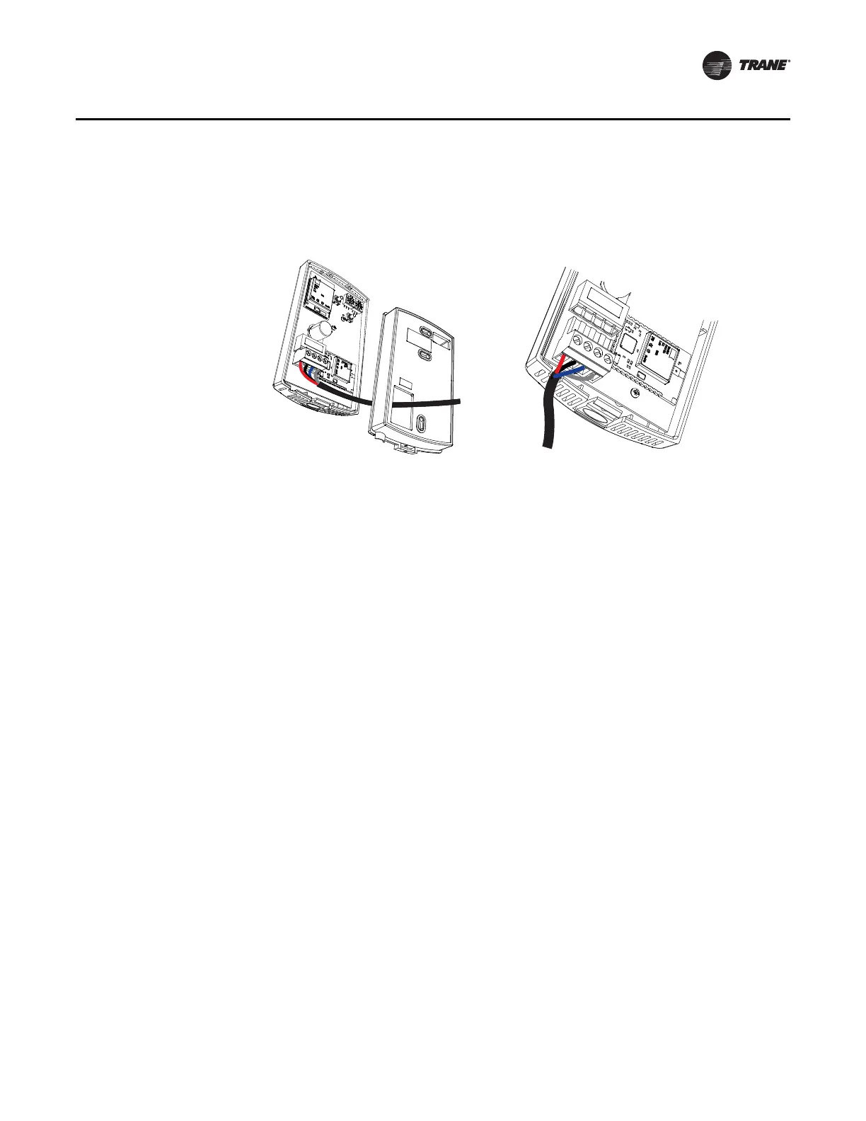
5. Route the wires from the WCI through either:
a. The opening in the back plate (Figure 5, a).
b. The bottom exit port (Figure 5, b).
Figure 5. Routing the wires through the WCI backplate (a) or bottom exit port (b)
6. Connect the wiring harness according to the illustration that is appropriate for your application:
Note: Wiring between a WCI and a controller cannot exceed 656 ft (200 m). If the wiring
harness does not provide enough length, use 18 AWG (24 pF/ft max.) communication
wire (Trane purple wire).
• To wire the WCI to a Tracer SC, see Figure 6, p. 14.
• To wire the WCI to a UC400 or a UC600, see Figure 7, p. 14.
• To wire the WCI to a BCI-I, see Figure 9, p. 15.
• To wire the WCI to a BCI-R, see Figure 10, p. 15.
7. Restore power to the controller.
Important: The WCI must be wired to the controller prior to power up in order to establish
network communication.
8. The network is ready to be formed. Refer to “Establishing the Network,” p. 17.