RT-SVX23D-EN 25
Installation
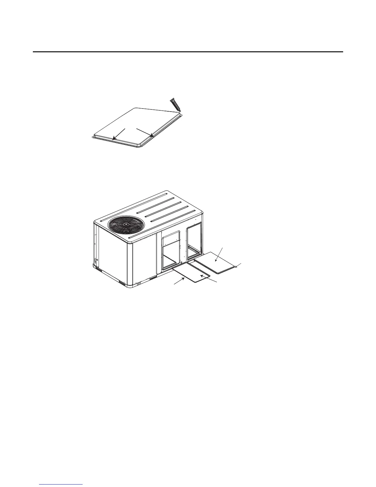
4. On original RETURN DUCT COVER, apply ¼” (6mm.) continuous bead of 500°F RTV sealant
around flange (opposite insulation side), as shown.
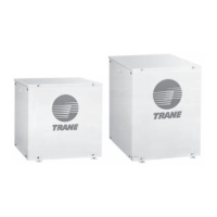
5. Slide RETURN DUCT COVER (insulation side up) into supply opening until inward edge of duct
cover engages with the 2 retaining clips on the duct flange. Secure outward edge of the duct
cover with two screws.
Note: If Unit is equipped with Return Air Smoke Detector, refer to field conversion instructions for
horizontal discharge before installing return air duct.
Note: Certain unit/electric heater combinations require a limit switch change out for horizontal
airflow applications. Refer to the following instructions to determine if this process is
required for the unit undergoing installation.
6. After completing installation of the duct covers for horizontal discharge, proceed to TCO-A
instructions.
TCO-A Instructions:
If the unit being installed is listed in the following table and is equipped with the corresponding
model number of factory installed electric heater package in the table, the limit control TCO-A must
be replaced with the extra limit control shipped in the heater compartment. Replace TCO-A
following the instructions in steps 1through 3 below. If the unit being installed does not have a
factory installed electric heater package or is equipped with a factory installed electric heater model
that does not correspond to any in this table, skip steps1 through 3 and go on to next step in the
installation process.
Figure 17.
Figure 18.
Insulation side
down
Supply duct cover
Insulation side up
Return duct
cover