RT-SVX23D-EN 55
Trouble Shooting
Method 2
To reset the system at the unit, cycle the unit power by turning the disconnect switch “Off” and then
“On”.
Lockouts can be cleared through the building management system. Refer to the building
management system instructions for more information.
Zone Temperature Sensor (ZTS) Service Indicator
The ZSM SERVICE LED is a generic indicator, that will signal the closing of a Normally Open switch
at any time, providing the Indoor Motor (IDM) is operating. This indicator is usually used to indicate
a clogged filter, or an air side fan failure.
The RTRM will ignore the closing of this Normally Open switch for 2 (±1) minutes. This helps
prevent nuisance SERVICE LED indications. The exception is the LED will flash 40 seconds after the
fan is turned “On” if the Fan Proving Switch is not made.
Clogged Filter Switch
This LED will remain lit the entire time that the Normally Open switch is closed. The LED will be
turned off immediately after resetting the switch (to the Normally Open position), or any time that
the IDM is turned “Off”.
If the switch remains closed, and the IDM is turned “On”, the SERVICE LED will be turned “On” again
after the 2 (±1) minute ignore delay.
This LED being turned “On”, will have no other affect on unit operation. It is an indicator only.
Fan Failure Switch
When the “Fan Failure” switch is wired to the RTOM, the LED will remain flashing the entire time
the fan proving switch is closed, indicating a fan failure, and it will shut the unit operations down.
Zone Temperature Sensor (ZTS) Test
Note: These procedures are not for programmable or digital models and are conducted with the
Zone Sensor Module electrically removed from the system.
Test 1 Zone Temperature Thermistor (ZTEMP)
This component is tested by measuring the resistance between terminals 1 and 2 on the Zone
Temperature Sensor. Below are some typical indoor temperatures, and corresponding resistive
values.
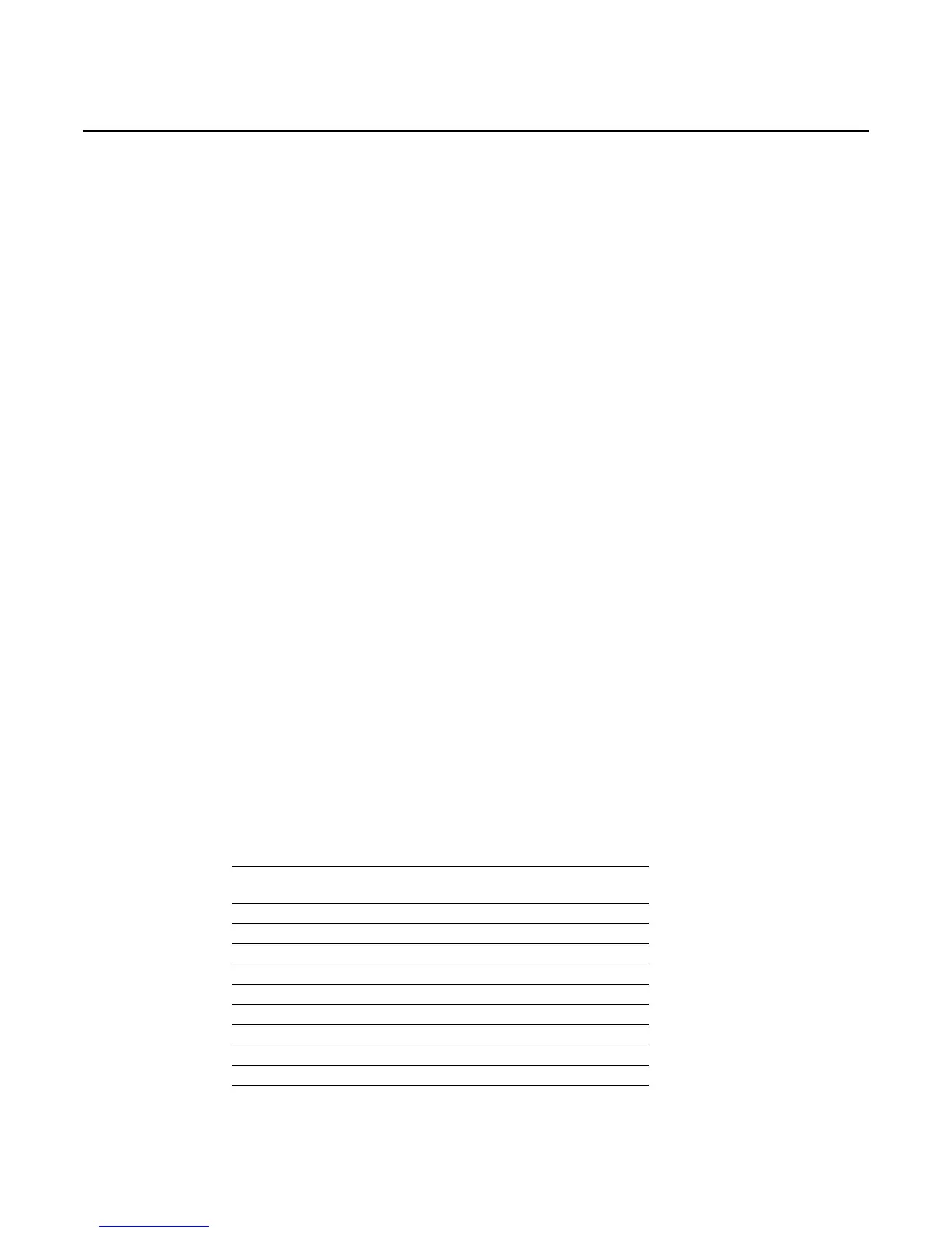
Test 2 Cooling Set Point (CSP) and Heating Set Point (HSP)
The resistance of these potentiometers are measured between the following ZSM terminals. Refer
to the chart above for approximate resistances at the given setpoints.
Table 10. Cooling (CSP) and heating setpoint (HSP)
Zone Temperature
Nominal ZTEMP
Resistance
Nominal CSP or
HSP Resistance
50 F° 10.0 C° 19.9 K-Ohms 889 Ohms
55 F° 12.8 C° 17.47 K-Ohms 812 Ohms
60 F° 15.6 C° 15.3 K-Ohms 695 Ohms
65 F° 18.3 C° 13.49 K-Ohms 597 Ohms
70 F° 21.1 C° 11.9 K-Ohms 500 Ohms
75 F° 23.9 C° 10.50 K-Ohms 403 Ohms
80 F° 26.7 C° 9.3 K-Ohms 305 Ohms
85 F° 29.4 C° 8.25 K-Ohms 208 Ohms
90 F° 32.2 C° 7.3 K-Ohms 110 Ohms