6
Installation of TI-500 RFTM remote wireless A/D Module
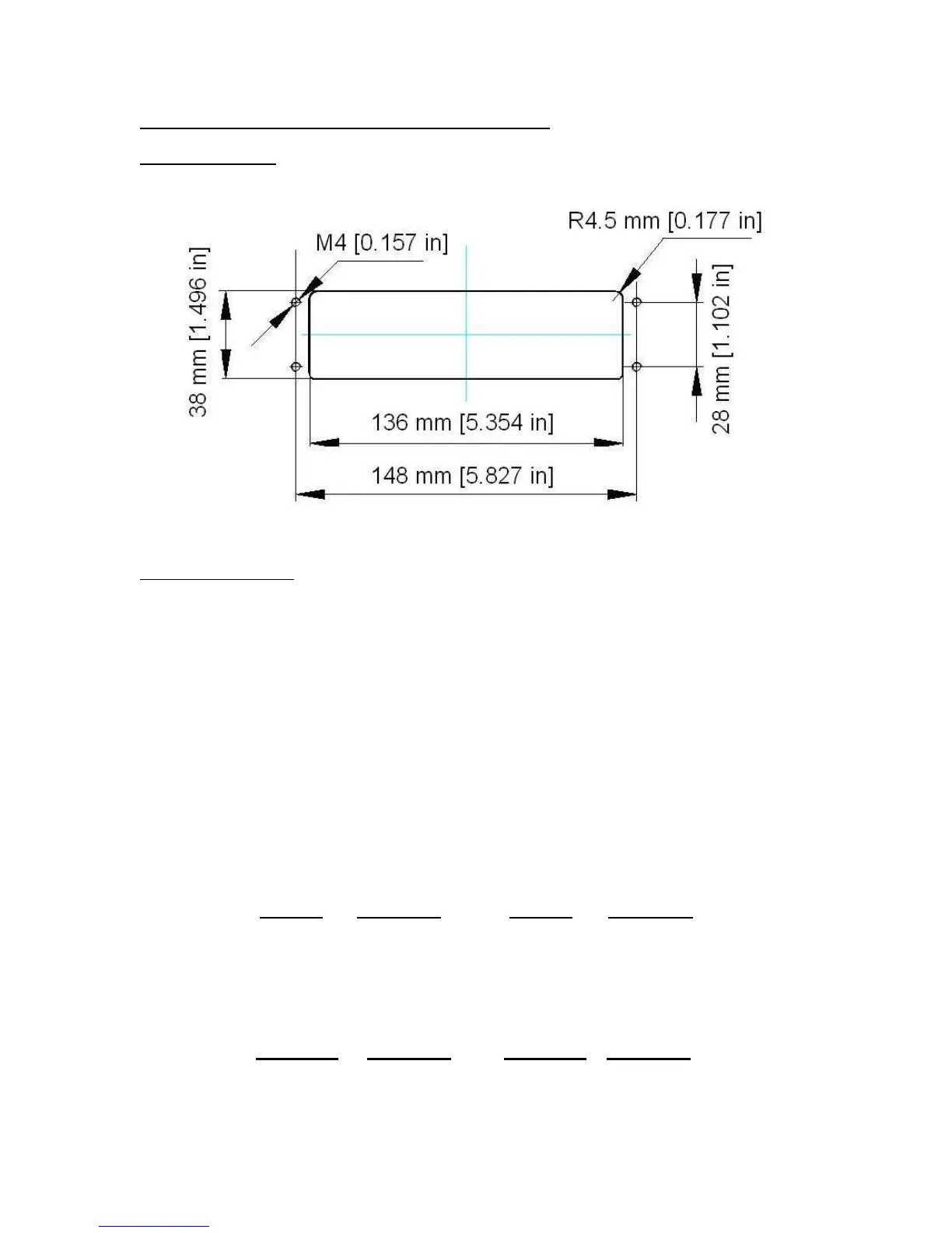
Physical installation
The remote wireless A/D module is designed to fit into a pre-defined opening:
An optional mounting bracket is also available.
Electrical Connections
The RF A/D module requires an external 6VDC power supply. Single channel units require
about 60 mA of current to drive four 350 ohm load cells (20 mA plus 10 mA per load cell). Dual
channel units require about 100 mA of current to drive eight 350 ohm load cells.
The RF A/D module will operate normally down to approximately 4 VDC whereupon it will indi-
cate a low battery condition.
The power leads are pre-wired to the inside of the RFTM. The red lead goes to the positive DC
terminal while the black lead goes to the negative DC terminal.
The RF A/D module also has at least one load cell input terminal or wiring harness. Each termi-
nal or harness can drive up to four 350 ohm load cells. The terminals are spring loaded; to open,
use a small screwdriver to press down on the orange tab. The harnesses should be spliced to
the load cell or j-box using the supplied butt splices.
Load Cell Input Terminal
S- - Signal E- - Excitation
S+ + Signal E+ + Excitation
NOTE: On dual RF A/D modules, each load cell terminal is marked 1-4, e.g. L/C3.
Load Cell Input Harness
White - Signal Black - Excitation
Green + Signal Red + Excitation
 Loading...