TABLE OF CONTENTS
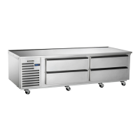
The serial tag is a permanently affixed sticker on
which is recorded vital electrical and refrigeration data
about your Traulsen product, as well as the model
and serial number. This tag is located on the upper
right interior wall of all TE-Series models.
I. THE SERIAL TAG
-1-
FORT WORTH, TX.
SERIAL MODEL
VOLTS Hz PH
TOTAL CURRENT AMPS
MINIMUM CIRCUIT AMPS
MAXIMUM OVERCURRENT PROTECTION AMPS
LIGHTS WATTS
HEATERS AMPS
REFRIGERANT TYPE OZ
DESIGN PRESSURE HIGH LOW
REFRIGERANT TYPE OZ
DESIGN PRESSURE HIGH LOW
370-60294-00 REV (A)
READING THE SERIAL TAG
• Serial = The permanent ID# of your Traulsen
• Model = The model # of your Traulsen
• Volts = Voltage
• Hz = Cycle
• PH = Phase
• Total Current = Maximum amp draw
• Minimum Circuit = Minimum circuit required
• Lights = Light wattage
• Heaters = Heater amperage
• Refrigerant = Refrigerant type used
• Design Pressure = High & low side operating
pressures and refrigerant charge
• Agency Labels = Designates agency listings
I. THE SERIAL TAG 1
II. GENERAL INFORMATION
a. Introduction 2
b. Model Designations 2
c. Wiring Diagrams 2
d. Installation - See Owner’s Manual 2
e. Cleaning 2
f. Tools 2
g. Refrigeration System Theory Of Operation 2
h. Air Flow Requirements 2
i. The Microprocessor Control 2
j. Control Locations 3
k. Specifications 3
l. Operating Data Chart 3
III. REMOVAL & REPLACEMENT OF PARTS
a. Louver Assembly 4
b. Evaporator Housing Cover 4
c. Removing The Drawer 4
d. Removing The Drawer Frame (slides) 4
e. Drawer Gaskets 5
f. Microprocessor Control 5
g. Condensate Drain Pan 5
h. Accessing Start Components 5
IV. REPLACING THE...
a. Condenser Fan Motor and/or Blade 6
b. Condenser Coil 7
c. Evaporator Fan 8
d. Evaporator Coil 9
IV. REPLACING THE... (cont’d)
f. Compressor 10
V. WIRING DIAGRAMS
a. 115V Refrigerator Models 11
VI. SERVICE PROCEDURES & ADJUSTMENTS
a. System Access 12
b. Sweat On Piercing Valves 12
c. Refrigerant Leak Check 12
d. Evacuating System 13
e. Charging System 13
f. System Clean-Up 14
g. Heater Test/Drawer Perimeter Heater 14
VII. ELECTRICAL OPERATION
a. Sequence Of Operation/Normal Operation 14
b. Sequence Of Operation/Defrost Mode 14
c. Component Function 15
d. Installation of Sensors 15
VIII. REPLACEMENT PARTS LISTING 16
IX. TROUBLESHOOTING 17