IV. b - REPLACING THE CONDENSER COIL
STEP 1: Remove the louver assembly as outlined in
section “III. a”.
STEP 2: Recover the refrigerant in the system
following the current EPA Guidelines for
refrigerant recovery.
NOTE: The use of reclaiming equipment is
required.
STEP 3: Disconnect the input and output lines to the
condenser coil at the soldered joints closest
to the condenser.
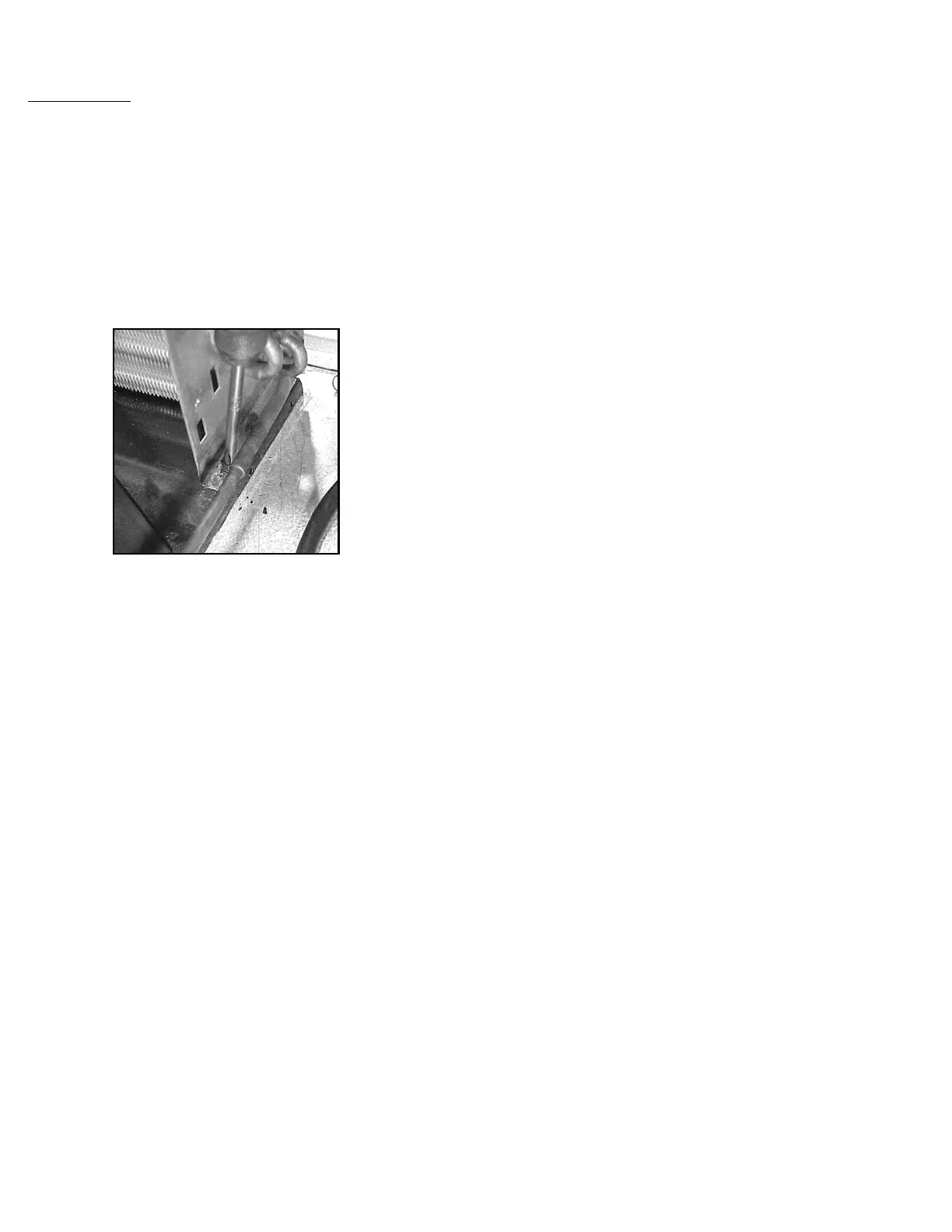
STEP 4: Remove the four (4) screws which secure the
condenser coil to the mounting brackets (see
illustration 1).
STEP 5: Remove the condenser coil.
STEP 6: Reverse the procedure to install the new
condenser coil.
STEP 7: Install a new drier.
STEP 8: Charge the refrigeration system as outlined
under “CHARGING SYSTEM” in “SERVICE
PROCEDUES AND ADJUSTMENTS.”
STEP 9: Reconnect power to the unit.
STEP 10: Reset the microprocessor control defrost time
settings to the correct time of the day.
WARNINGS:
1) DISCONNECT THE ELECTRICAL POWER TO THE
MACHINE AND FOLLOW LOCKOUT/TAGOUT
PROCEDURES.
2) THIS PROCEDURE REQUIRES THE USE OF REFRIG-
ERANTS. BE CERTAIN THE WORK AREA IS WELL
VENTILATED. SAFETY GOGGLES AND GLOVES
SHALL BE WORN SINCE REFRIGERANTS MAY CAUSE
BURNS TO THE SKIN.
-7-
Illustration 01