TT31 Transponder Installation Manual 1 February 2010
00455-00 Issue AJ
______________________
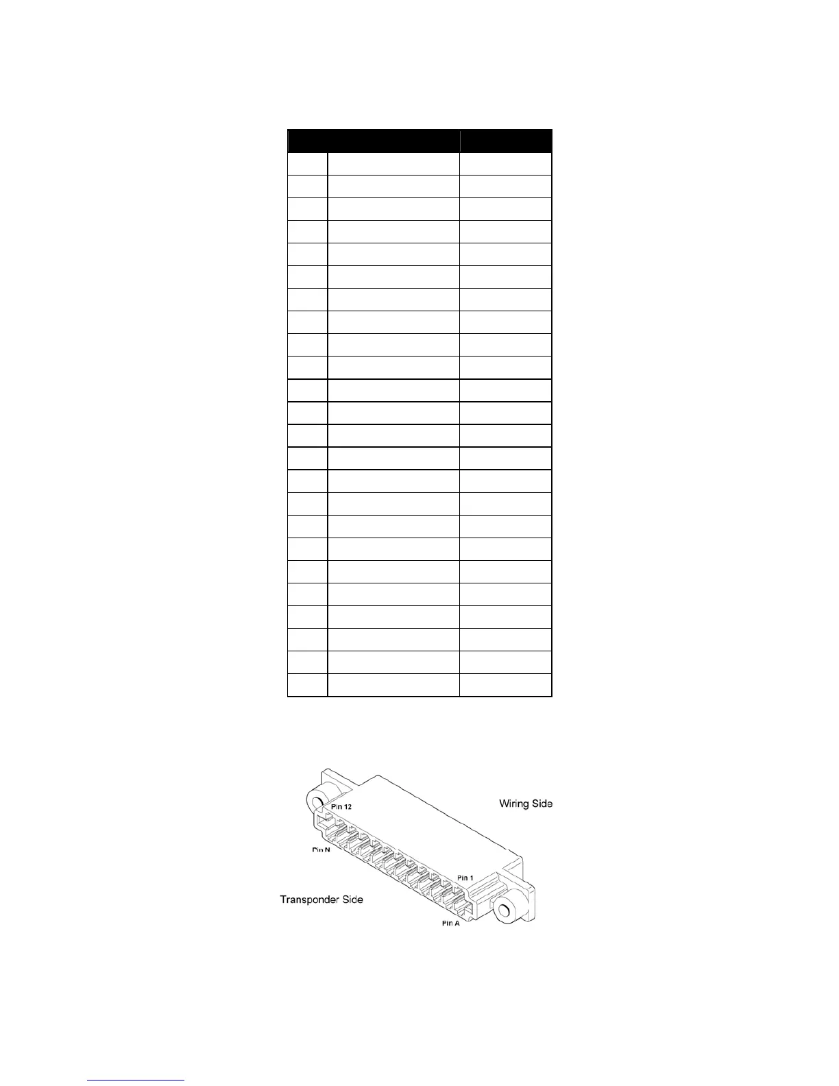
5.4.1 Primary Interface – Pinout
Pin Signal Direction
1
Ground -
2
Lighting 14V Input
3
Lighting 28V Input
4
Suppress I/O * Bi-directional
5
Squat Switch In * Input
6
Serial Alt Out * Output
7
Serial Alt In * Input
8
Altitude D4 Input
9
Suppress In Input
10
Standby Switch Input
11
11-33V DC -
12
11-33V DC -
A
Ground -
B
Altitude B4 Input
C
Altitude B2 Input
D
Altitude C1 Input
E
Altitude B1 Input
F
Ident Switch In Input
H
Altitude C4 Input
J
Altitude A4 Input
K
Altitude A2 Input
L
Altitude C2 Input
M
Altitude A1 Input
N
Do Not Connect * -
*: These signals are different to the KT76A/KT78A pinout; on the KT76A and KT78A these signals
are not usually connected in the aircraft.
The following diagram shows the connector orientation as it would be fitted to the mounting tray.
Page 8 Trig Avionics Limited