TT31 Transponder Installation Manual 1 February 2010
00455-00 Issue AJ
______________________
The TT3 at, or
the form selected
lay of uplinked Traffic Information Service messages. It is an
is limited to the coverage areas of those radars. There is no TIS provision outside
the USA.
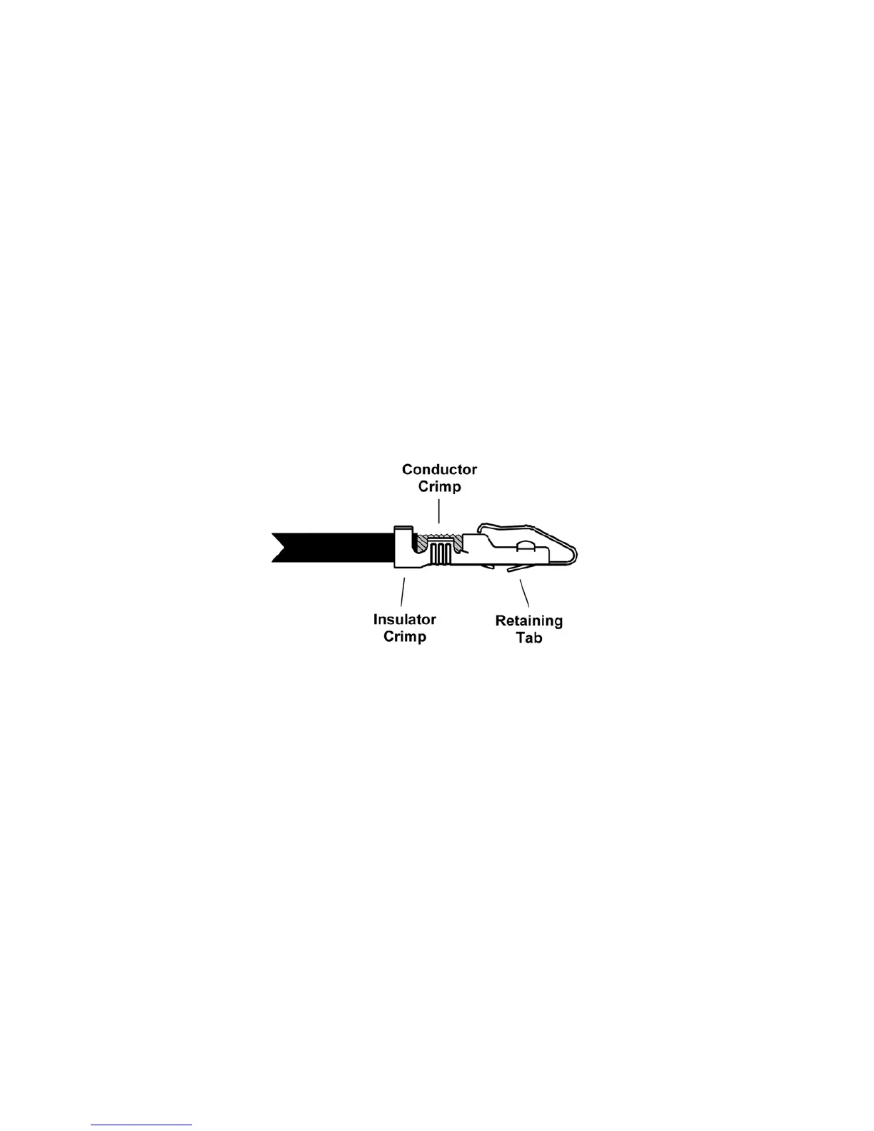
5.6 Molex Crimp Terminals
le
sing both the conductor
1 GPS input can recognise the industry standard “Aviation” format, the NMEA 0183 form
at used by certain Freeflight and NexNav GPS sensors; the interface speed can be
between 4800, 9600 and 19200 bps.
5.5.11 TIS Traffic Output
The TIS traffic output supports the disp
RS232 output on the 12 way secondary connector. The TT31 TIS output can drive the Trig proprietary
traffic protocol, and can also support the format used by certain Garmin handheld displays, including
the 495, 496, 695 and 696.
Note: TIS is a Mode S uplink service that is provided by some US approach radars. TIS
coverage
The Molex connector contacts should be wired with wire of 18-24 AWG. The contacts are compatib
wi
th a wide range of crimp tools. Ensure that the contact has been crimped u
crimp and the insulator crimp.
Once crimped, the contacts should be slotted into the rear of the connector shell. Push the contact in
until the retaining tab clicks into place. Tug gently to confirm the contact is locked in place.
The contacts can be easily removed using the Molex removal tool, or equivalent. This is pushed gently
into the connector shell from the side opposite from the wire entry, and lifts the retaining tab from the
stop, allowing the contact to be eased out by pulling on the wire.
5.7 Antenna Installation
The antenna should be installed according to the manufacturer’s instructions.
The following considerations should be taken into account when siting the Antenna.
The antenna should be well removed from any projections, the engine(s) and propeller(s). It
should also be well removed from landing gear doors, access doors or others openings which
will break the ground plane for the antenna.
The antenna should be mounted on the bottom surface of the aircraft and in a vertical position
when the aircraft is in level flight.
Avoid mounting the antenna within 3 feet of the ADF sense antenna or any COMM antenna
and 6 feet from the transponder to the DME antenna.
Page 12 Trig Avionics Limited