TT31 Transponder Installation Manual 1 February 2010
00455-00 Issue AJ
______________________
5.7.2 BNC Connector
This section describes the technique for attaching the antenna cable to the supplied blind-mate BNC
connector.
If a low-loss cable is needed that has too large a dielectric diameter to fit the supplied blind-mate BNC
connector, a short length (up to 150mm or 6 inches) of smaller cable may be used with suitable mating
connectors to adapt to the transponder connector.
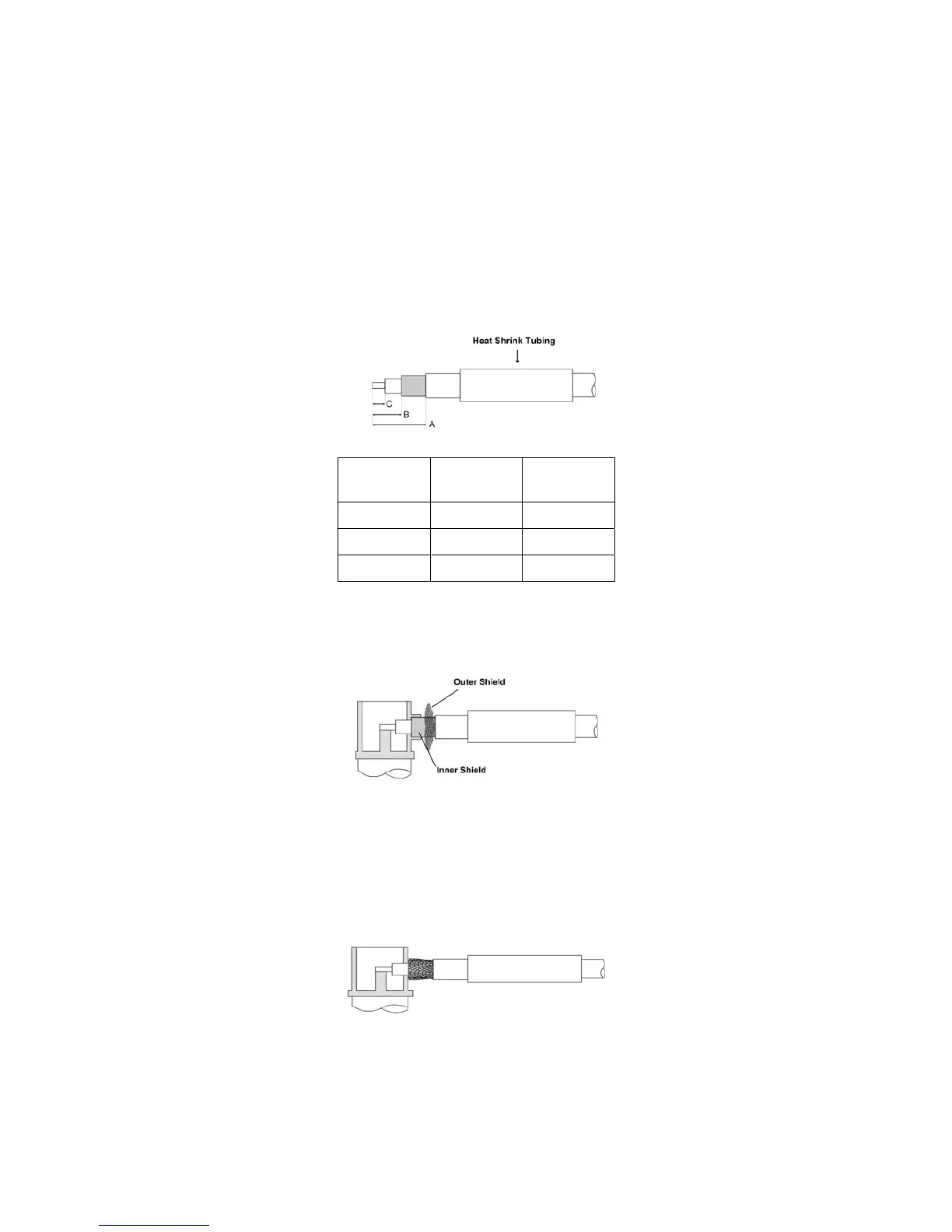
Strip back the coax cable to the dimensions in the table, as shown in the diagram below. Slide
25 mm (1 inch) of heat shrink tubing over the cable.
Dimension Cut size
(mm)
Cut size
(inches)
A 12.7 0.5
B 6.4 0.25
C 3.2 0.125
Insert the cable into the connector – the inner conductor should align with the centre contact,
the inner shield should be inside the body of the connector and the outer shield should be
outside the body.
Solder the centre conductor to the centre contact, aligning the conductor with the slot in the
contact. Avoid excess solder heat on the centre BNC conductor pin.
Solder the inner shield to the inside of the connector body by applying a soldering iron to the
body and running solder into the gap. Try to avoid excess solder heat on the connector body.
Solder the outer shield to the outside of the connector body. Avoid excess solder heat on the
connector body.
Trig Avionics Limited Page 15