TT31 Transponder Installation Manual 1 February 2010
00455-00 Issue AJ
______________________
le and
hould be protected to avoid loss of efficiency as a result of the
ntenna feeders shall be installed in such a way that a minimum of
s
ith low enough loss per metre that meets the above
ight bends or from momentary kinking during installation.
not return to full performance when straightened.
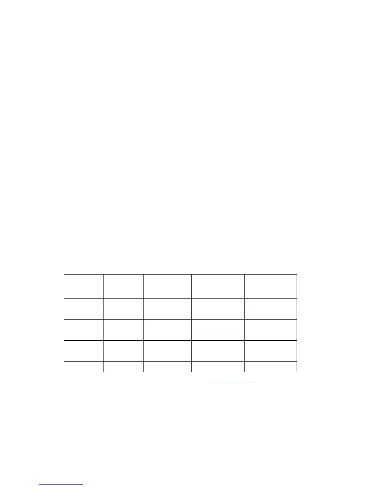
The following table is a guide to the maximum usable lengths of some common cable types. Actual
.
re at
1090MHz
Specialists Type
W
here practical, plan the antenna location to keep the cable lengths as short as possib
avoid sharp bends in the cable to minimise the VSWR.
To prevent RF interference, the antenna must be physically mounted a minimum distance of 3
feet from the TT31 Mode S transponder.
Electrical connection to the antenna s
presence of liquids or moisture. All a
RF energy is radiated inside the aircraft.
5.7.1 Antenna Cable
The TT31 is designed to meet Class 1 requirements with an allowance of 2 dB for loss in the connector
and cable used to connect it to the antenna. Excessive loss will degrade both transmitter output power
and receiver sensitivity.
Allowing 0.25dB loss for the connector at each end of the antenna cable assembly leaves an allowance
of 1.5dB maximum loss for the cable itself.
An acceptable cable:
Has less than 1.5dB loss for the run length needed
Has a characteristic impedance of 50 Ohms
Has double braid screens or has a foil and braid screen
Once the cable run length is known, a cable type w
requirements can be chosen. Longer runs require lower loss cable.
NOTE: Low loss cable typically uses foamed or cellular dielectrics and foil screens. These make such
cables especially prone to damage from too-t
Once kinked, these cables do
cable loss varies between manufacturers, there are many variants, and the table is therefore based on
typical data. Use it as a guide only and refer to the manufacturer’s data sheet for your specific chosen
cable for accurate values
Max Length
in Metres
Max Length
in Feet
Insertion Loss
dB/met
MIL-C-17 Cables Electronic Cable
2.54 8’ 4” 0.59 M17/128 (RG400)
3.16 10’ 4” 0.47 3C142B
3.81 12’ 6” 0.39 M17/112 (RG304)
5.25 17’ 3” 0.29 M17/127 (RG393) 311601
6.42 21’ 1” 0.23 311501
8.22 26’ 11” 0.18 311201
12.59 41’ 3” 0.12 310801
Contact Electronic Cable Specialists on +1 414 421 5300 or www.ecsdirect.com for their data sheets
When routing the cable, ensure that you:
Route the cable aw
.
ay from sources of heat.
Route the cable away from potential interference sources such as ignition wiring, 400Hz
generators, fluorescent lighting and electric motors.
Trig Avionics Limited Page 13