TT31 Transponder Installation Manual 1 February 2010
00455-00 Issue AJ
______________________
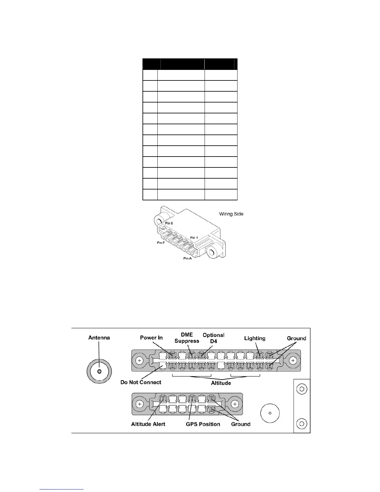
5.4.2 Secondary Interface - Pinout
Pin Signal Direction
1
Ground -
2
TIS Traffic Out Output
3
GPS Position In Input
4
Reserved Input
5
Audio Mute In Input
6
Altitude Alert Output
A
Ground -
B
Audio + Output
C
Audio - Output
D
Reserved -
E
Reserved -
F
Reserved -
5.4.3 Orientation Diagram
To assist in connector orientation, the following example shows a typical set of connections. This
diagram shows the expected connector positions when viewed from the transponder side of the tray,
looking into the tray from the front. In the example shown the aircraft uses a 14 volt lighting bus, a
parallel altitude encoder, a DME with simple suppression output, a GPS with serial position output, and
a simple lamp for the altitude alerter. This example is representative of a simple fixed gear 14 volt
aircraft.
Trig Avionics Limited Page 9