10 PRELIMINARY: TR-FFT Fire Fighter’s Telephone Manual — LS10309-001TR-E:A 04/28/2021
Prerequisites for Installation Electrical Specifications
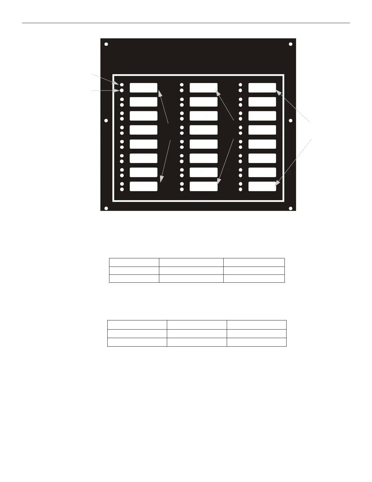
Figure 2.4 TR-24Z-EXT- Expander Front View for Zone 49 - 72
2.4 Electrical Specifications
2.4.1 Power Requirements
The voltage for the TR-FFT must be a power-limited, filtered, non-resettable nominal 24 VDC source. The voltage source
must be within the range of 17-29 VDC.
2.4.2 Current Ratings
The maximum current ratings required to determine the backup battery requirements for the alarm (active) and the standby
conditions over the input voltage range of 17-29 VDC are shown in Table 2.2.
Active
(green)
Trouble
(amber)
Zone 49 -
Zone 56
Zone 57
Zone 64
Zone 65
Zone 72
Circuits Voltage Current
SLC Circuits 17 V 150 mA
Audio Circuits 18 V 53 mA
Table 2.1 Electrical Ratings
Model Active Standby
TR-FFT 230 mA 120 mA
TR-24Z-EXT 25 mA 10 mA
Table 2.2 TR-FFT Current Draw